


Page 23
13HPD SERIES
DEFROST THERMOSTAT SWITCH (S6)
The defrost thermostat as illustrated in figure 1 is located on the liquid line between the CTXV and the distributor. When
defrost thermostat senses 42°F (5.5°C) or cooler, the thermostat contacts close and send a signal to the defrost control to
start the defrost timing. It also terminates defrost when the liquid line warms up to 70°F (21°C).
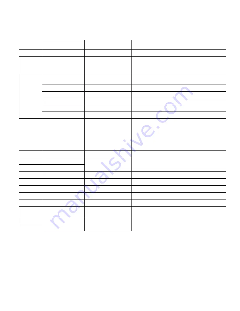
Table 5. Defrost Control Inputs, Outputs and Configurable Settings
Control Loca-
tion
Control Label or
Description
Purpose
Function
P1
TEST
Test Mode
See Test Mode on page 22 for further details.
P1
30, 60, 90
Defrost Temperature
Termination (Jumper) Pins
The defrost control as illustrated in figure 20 has valid selections
which are: 30, 60, and 90°F (−1, 16 and 32°C). The shunt termination
pin is factory set at 50°F (10°C). If the temperature shunt is not
installed, the default termination temperature is 90°F (32°C).
P2
W1
24VAC Thermostat Input /
Output
24VAC input/output from indoor thermostat to indoor unit.
C
24VAC Common
24VAC common
L
Thermostat Service Light
Thermostat service light connection.
R
24VAC
24VAC
O
Thermostat Input
Reversing valve solenoid.
Y1
Thermostat Input
Controls the operation of the unit.
P5
DELAY
Delay Mode
The defrost control has a field−selectable delay to reduce occasional
sounds that may occur while the unit is cycling in and out of the defrost
mode. When a jumper is installed on the DELAY pins, the compressor
will be cycled off for 30 seconds going in and out of the defrost mode.
Units are shipped with jumper installed on DELAY pins.
NOTE − The 30 second off cycle is NOT functional when
jumpering the TEST pins on P1.
P6
TST, PS DF, C, R, O, Y1
Factory Test Connectors
Factory Use Only.
DS1
RED LED
Diagnostic LED
Valid states for defrost control’s two LEDs are OFF, ON and
FLASHING which indicate diagnostics conditions that are described
in table 4.
DS2
GREEN LED
FAN
TWO CONNECTORS
Condenser Fan Operation
These two connections provide power for the condenser fan.
O OUT
O OUT
24VAC output
24VAC output connection for reversing valve.
LO−PS
LO−PS
Low−Pressure Switch
Not Used.
DF
DF
Defrost Thermostat
Defrost thermostat connection points.
Y1 OUT
Y1 OUT
24VAC Common Output
24VAC common output, switched for enabling compressor contactor.
HS−PS
HS−PS
High−Pressure Switch
(Optional)
Not Used.
L
L
Service Light Output output
24VAC service light output.
24V
24V
24VAC output
Not Used.