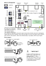
Audio Inputs
Twist together
100V speaker line
1
2
3
Line Input
Female XLR
Socket
Twist together
Low Z Speaker feed
1
2
3
1
2
3
0V
Unbalanced Line Out (Rec Out)
1
2
3
0V
Balanced Line Out
**IMPORTANT
**
If using a 100V line signal, you
MUST set the attenuator to the
highest setting (J1 + J5)
BEFORE turning your TDS1 on
for the first time. There is a risk
of damaging the input circuits if
you ignore this advice.
INPUT ATTENUATOR
Link Out
Link In
J1 J2
J10
2V
J9
5V
J8
15V
J7
35V
J6
75V
J5
125V
1
0
0
V
L
in
e
I
n
0
d
B
L
in
e
I
n
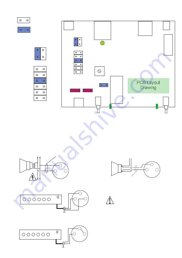
As shown in the drawing,
the attenuator is selected
(J1) and the unit set for a
15V (J8) input signal.
This might be typical of a
low impedance loudspeaker where the signal is taken from directly across the loudspeaker.
Always start with link in position J5 and move towards J10 to set a sensible volume with the
gain control in mid position. LED 5 should flash faintly in sympathy with the input signal.
3 Hour Timer J17
Enabled Link=In
Line Fuse 100mA x2
Auto / Man
Switch
Active
LED
Power On/Off
Indicator
LED
100mA
PowerSupply
Fuse 20mm
J5
J10
J17
A
tt
e
n
u
a
to
r
L
in
k
s
J1 J2
1
0
0
V
L
in
e
I
n
0
d
B
L
in
e
I
n
Telephone
Line In
Telephone
Line Out
XLR Audio
Input
Facilities
Socket
Power
In
PCB Layout
Drawing
NOTE: Not to scale. Drawn for clarity
100V
2V
VR1 Adjust
Send Volume
FS2
FS1
FS5
LED 5 Compressor Control
M
ic
ro
p
ro
c
e
s
s
o
r


