background image

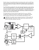
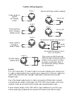
Audio Inputs

Twist together

100V speaker line

1

2

3

Line Input
Female XLR
Socket

Twist together

Low Z Speaker feed

1

2

3

1

2

3

0V

Unbalanced Line Out (Rec Out)

1

2

3

0V

Balanced Line Out


**IMPORTANT

** 

If using a 100V line signal, you 
MUST set the attenuator to the 
highest setting (J1 + J5) 
BEFORE turning your TDS1

 S/R 


on for the first time.  There is a 
risk of damaging the input circuits 
if you ignore this advice.


INPUT ATTENUATOR

Link Out

Link In

J1 J2

J10

2V

J9

5V

J8

15V

J7

35V

J6

75V

J5

125V

1

0

0

V

 L

in

e

 I

n

0

d

B

 L

in

e

 I

n

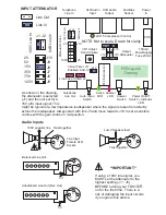
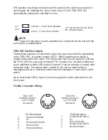
As shown in the drawing, 
the attenuator is selected 
(J1) and the unit set for a 
15V (J8) input signal. This 

might be typical of a low impedance loudspeaker where the signal is taken from directly 
across the loudspeaker. Always start with link J5 and move towards J10 to set a sensible 
volume with the gain control in mid position.

3 Hour Timer J17

Enabled Link=In

Line Fuse 100mA x2

Auto / Man 

Switch

Active 

LED

Power On/Off 

Indicator 

LED

100mA 

PowerSupply 

Fuse 20mm

J5

J10

J17

A

tt

e

n

u

a

to

L

in

k

s

J1 J2

1

0

0

V

 L

in

e

 I

n

0

d

B

 L

in

e

 I

n

Telephone 

Line In

Telephone 

Line Out

XLR Audio 

Input

Facilities 

Socket

Power 

In

PCB Layout

Drawing

NOTE: Not to scale. Drawn for clarity

100V

2V

VR1 Adjust 

Send Volume

FS2

FS1

FS5

LED 5 Compressor Control

M

ic

ro

p

ro

c

e

s

s

o

r

Answer 

LED

Answer 

Switch

XLR Audio 

Output

J12

J13

J14

J15

Output 

Attenuator

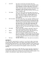
Summary of Contents for TDS1 S/R

Page 1: ...re starting First of all plan your installation and decide where to fit your TDS1 S R It needs to be close to a telephone socket have mains power and an audio signal feed In MANual mode you will be us...

Page 2: ...and the unit set for a 15V J8 input signal This might be typical of a low impedance loudspeaker where the signal is taken from directly across the loudspeaker Always start with link J5 and move towar...

Page 3: ...connected together and both of these connect to the screen braid of the incoming audio feed cable The signal source can be any line level signal from 0 5V up to a 100V line speaker feed Taking the out...

Page 4: ...listen to comments Release the switch when the answer is finished Note that switching by this method allows the TDS1 S R to be used as the listening end of a telephone hookup system where one location...

Page 5: ...tation will quickly determine the optimum settings Release the call The TDS1 S R should clear down and reset Redial the TDS1 S R telephone line The TDS1 S R should again answer the call and connect to...

Page 6: ...nt to extend the capabilities of the TDS1 S R It enables remote AUTO MAN switching and allows a remote Active light to be used The remote light can be very useful to indicate the TDS1 S R is in use an...

Page 7: ...ly and insulate between pins Ensure that the switch on the TDS1 S R is set to MANual if you wish to use remote switching Otherwise the remote AUTOmatic mode will not work Socket 1 Press switch to Hold...

Page 8: ...is important not to allow anyone to listen in Automatic Mode When set to AUTOmatic there is nothing to do the first incoming telephone caller is automatically connected to the sound system and remain...

Page 9: ...tions where the volume is not adequate i e many miles from the serving telephone exchange use a handset with jack audio output This allows connection from the telephone line into a line input i e CD o...

Page 10: ...connect the telephone line and test FS1 and FS2 5 No Audio Check all the audio wiring for continuity Ensure the audio signal is applied between XLR pins 2 and 3 6 Storm There was a storm and now the T...

Page 11: ...ow anyone to dial into a sound system and listen live to the program audio feed In the AUTOmatic mode the TDS will answer the first incoming telephone call and connect the caller to the audio In the M...

Page 12: ...TDS1 S R Manual Iss1 cdr...

Reviews: