background image

95


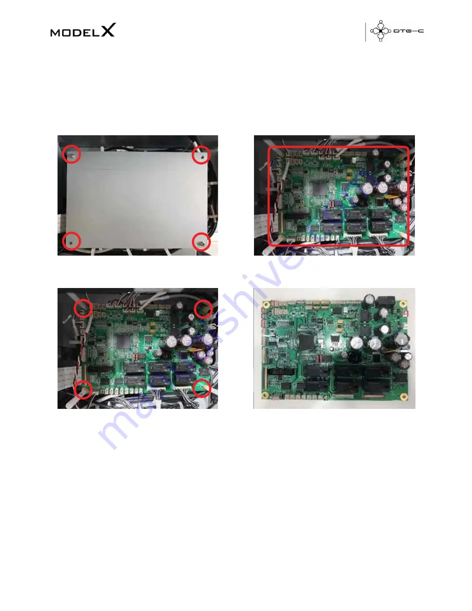
9.3  Replacing MODEL X DTG-C Sub Control Board 

1.


Turn


off


the


printer


power.


2.


Remove


the


printer


top


cover


case.


3.


Loosen


the


four


bolts


and


remove


the


SCB


cover.


5.


Loosen


the


four


support


bolts


and


remove


the


SCB.


4.


Remove


the


harness


connected


to


SCB.


6.


Assemble


the


new


SCB


and


connect


the


harness.


7.


Assemble


the


SCB


cover.


8.


Assemble


the


printer


top


cover


case.


9.


Turn


on


the


printer


power.


Summary of Contents for Model X

Page 1: ......

Page 2: ...Inc Intel is a registered trademark of Intel Corporation PowerPC is a registered trademark of International Business Machines Corporation Adobe Photoshop Elements Lightroom and Adobe RGB are registere...

Page 3: ...OCUMENT HEREINAFTER REFERRED TO AS THE WRITER HEREBY DISCLAIMS ALL WARRANTIES EXPRESSED IMPLIED OR OTHERWISE INCLUDING WARRANTIES OF MERCHANTABILITY FITNESS FOR A PARTICULAR PURPOSE AND NON INFRINGEME...

Page 4: ...17 3 1 1 Setting Platen 17 3 1 2 Stored Job 17 3 1 3 USB Printing 18 3 2 Maintenance Screen 19 3 2 1 Nozzle Check 20 3 2 2 Automatic Head Cleaning 21 3 2 3 Manual Head Cleaning 22 3 2 4 Agitating Whi...

Page 5: ...5 2 3 Factory Reset of Adjustment Setting 57 5 2 4 Setting Obstacle Sensor 57 5 3 Operation Panel Messages 58 5 3 1 Terminology 58 5 3 2 Overview Of Status 58 5 3 3 Messages 59 5 3 4 Service Call 62 6...

Page 6: ...8 7 4 Diagnostic Flow for Initialize Sequence 79 7 5 Table Homing Detail 82 7 6 Android Screen Error 83 8 HARDWARE INFORMATION 8 1 Harness Schematics With PCBS 84 8 2 Harness Connections on SCB 85 8 3...

Page 7: ...x 20 Medium 320 x 457mm 12 6 x 18 Small 266 x 330mm 10 5 x 13 Table Height Adjustment Automatic 1 25 depends on bed height Ink Type Pigment garment ink Ink Channels K C M Y W W Ink Delivery System Car...

Page 8: ...he T shirt here A medium sized platen is already installed Optional larger and smaller platens are available Sub Power It turns machineon off USB Port 2 0 Normally leave it on When the machine is not...

Page 9: ...sage will be displayed when it needs to be replaced Carriage Underneath there is the print head and the head nozzle It moves left and right when printing The carriage requires regular cleaning Head Ca...

Page 10: ...maintenance periodically But it requires manual maintenance weekly the ink in the cartridge could settle and or coagulate causing poor image quality or printer failure If weekly maintenance is neglect...

Page 11: ...or holding this button 4 Select platen height adjustment method auto or manual 5 Select from recent print jobs 6 Select to access the maintenance menu 7 Select to access the USB to find print jobs on...

Page 12: ...tly printed information The user can view and print a list of print image data stored in a USB Item Item name Description 1 View recently printed job from image 2 Select highlighted job for reprinting...

Page 13: ...job dialogue box Item Item name Description 1 Check and select print files on the USB drive 2 Select highlighted job for reprinting 3 Save the highlighted job don t allow deletion 4 Save highlighted j...

Page 14: ...able first 2 Access parts replacement screen 3 Access automatic print head cleaning screen 4 Release carriage to perform manual maintenance 5 Adjust platen height 6 Set platen in or out must be in to...

Page 15: ...c 2 Access IP address and network settings menu 3 Access temp menu to change between C and F 4 Activate or deactivate obstruction sensor turning off may result in carriage damage 5 Reset printer to fa...

Page 16: ...ion 1 Print head adjustment pattern 2 Print platen adjustment pattern 3 Print adjustment pattern for print position 4 Access new table alignment menu 5 Set or eject platen 6 Manually adjust platen hei...

Page 17: ...ay the usage date of replacement for the replacement parts And perform replacing process for each part Left spitting box sump Print head carriage Right spitting box sump Maintenance station capping st...

Page 18: ...White ink bay Cyan and Black ink bay Magenta and Yellow ink bay Return to home screen...

Page 19: ...nect waste ink bottle tube to valve on the right back side ofprinter 3 Connect the power cable and turn on the AC power switch Power Connector AC Power Switch 4 Insert ink cartridge WARNING The printe...

Page 20: ...on t open cartridge cover or cut power 5 Hold down the sub power button for more than 3 seconds Toturn the power on hold down the sub power for more than 3 seconds Toturn the power off hold down the s...

Page 21: ...2 Setting platen For printing platen should be set as close to head as possible REFERENCE This printer uses ethernet to send the printing data If ethernet is not set up you will need to use an externa...

Page 22: ...sly up ordown 2 2 2 Auto Manual platen adjustment Auto Manual You can choose automatic or manual height adjustment On the automatic mode the height of platen is adjusted automatically when the platen...

Page 23: ...to print position you have to select Eject to return to the position for placing T shirt on platen Stop This is used to stop the platen When the platen is moving this is activated 1 1 1 1 Eject This r...

Page 24: ...en in manual mode this dialogue box is displayed Lower the height of platen 2 2 5 Cancel Pause and Resume printing Press the CANCEL to cancel the printing On the printing press to stop printer is paus...

Page 25: ...t remember the requirements below 1 At anytime the MODEL X DTG C can receive or pend the print data 2 But to start printing platen should be set to print start position Toset the platen press button L...

Page 26: ...3 USER INTERFACE 3 1 Home Screen 3 1 1 Setting Platen Please refer 2 2 3 Setting Platen...

Page 27: ...rformance The user can access these functions through this tab Built in scheduled maintenance is listed below Every hour White ink circulation Every 3 hours White channel cleaning Every 12 hours All i...

Page 28: ...ozzle transparent media is required 2 Prepare medium size platen Nozzle check pattern is based on medium platen aligned on top center Additionally all built in patterns are based on this platen 3 Atta...

Page 29: ...ines the print head will need to be cleaned This printer has an automatic head cleaning function Youcan press this button to perform automatic print head cleaning In this box user can choose the chann...

Page 30: ...aintenance unit Using lint free swab wetted with cleaner liquid clean the wiper of maintenance unit 3 2 3 Manual Head Cleaning If nozzle status has not recovered with automatic head cleaning then you...

Page 31: ...and coagulation When this alarm dialogue is displayed you have to shake the white cartridges smoothly to prevent damaging the ink bag inside of cartridge This dialog will be closed by opening cartrid...

Page 32: ...2 7 Empty the Waste Ink Bottle When the waste ink bottle is full the following message is displayed on the touch panel You can check the amount of waste ink on the Status Panel and reset the waste in...

Page 33: ...the print quality may not be good You will need to perform this adjustment process These functions can be performed through the Maintenance screen 1 Prepare the A4 transparent media and medium size pl...

Page 34: ...ned or colour is not clear this adjustment may improve the result Select this button the pattern of adjusting head is printed After pattern is printed find an appropriate adjustment value from the pri...

Page 35: ...printing position can be adjusted If the print result has a line of horizon you need to do this function Select this button for print position Find an appropriate adjustment value from the print resu...

Page 36: ...st colour is 6 but horizontal lines on both sides are misaligned In this case check horizontal lines for one pattern above and one pattern below of the square The horizontal lines for 2 and 6 are misa...

Page 37: ...After printing the pattern of adjusting printing position you have to find appropriate value Values can be selected between 4 0 4 0 in increments of 0 1mm Tomove the print position to the A direction...

Page 38: ...hown as below Each button indicates the parts requiring replacement Select the button the part replacement dialogue box is displayed Also it shows the information of part counts and replaced date The...

Page 39: ......

Page 40: ...ide or center of the printer as below Rotate the black lever counter clockwise until the arrow on the lever aligns with the arrow marked C below When the triangles are aligned the carriage is unlocked...

Page 41: ...5 Remove encoder strip on print head 6 Release encoder strip on left spitting box side 7 Hang encoder strip on the left spitting box side 8 Insert encoder strip into print head...

Page 42: ...9 Hang Encoder Strip on the maintenance unit side 10 Move print head to maintenance unit side 11 Turn on the printer power...

Page 43: ...4 1 2 Carriage Unit Before replacing print head it is necessary to flush the ink out of the print heads Select the maintenance menu and then Ink Path Control and flush ink from system...

Page 44: ...to be released manually shut down printer at power switch and release carriage from maintenance station by rotating the white lever counterclockwise to align triangles Then slide carriage to middle o...

Page 45: ...17 inch Reference 4 1 1 6 Remove the guide lock linkage 8 Attach the jigs 5 Disconnect the vertical arm of the spring and remove it 7 Push the carriage all the way to the left side of the machine unti...

Page 46: ...of the carriage timing belt from the back of the carriage 12 Remove the carriage and HRB cover 13 Remove the FFC harness and ink tube Reference 4 1 3 14 Replace the carriage 15 Assemble in reverse or...

Page 47: ...e 1 Turn off the printer power 2 Open the printer top cover 3 Remove the cover of carriage and MODEL X DTG C junction board 4 Remove the Ink tube attached to the old carriage and insert the cap to end...

Page 48: ...5 Separate the tube from the plate tube rhe loosen one bolt 6 Remove the ink tube fix bracket loosen the fourbolts 7 Remove the Ink tube on the ink supply unit Reference 4 4 1...

Page 49: ...8 Assemble the ink tube to the plate tube and ink tube fix bracket Align the guide line to the middle of the plate tube hole 9 Assemble the ink tube to the carriage...

Page 50: ...10 Assemble the new ink tube to the ink supply unit 11 Turn on the printer power...

Page 51: ...rence 4 1 1 3 Remove the carriage unit reference 4 1 2 4 Remove the spring pressure roller remove using long nose pliers 5 Push the pressure roller inward and remove the timing belt 6 Assemble a new t...

Page 52: ...ing pressure roller and remove the timing belt reference 4 1 5 4 Push the pressure roller inward to remove it Pull to the marked hole and remove 5 Assemble the new pressure roller by pushing it outwar...

Page 53: ...ference 4 1 1 3 Remove the carriage unit Reference 4 1 2 4 Remove the timing belt x axis Reference 4 1 5 5 Remove the harness connected to the DC motor 6 Loosen the two bolts 7 Assemble the new DC mot...

Page 54: ...rd Module 4 1 7 1 Main Controller Board Unit 1 Turn off the printer power 2 Remove the printer top cover case 3 Remove the CTL cover Loosen the four bolts 4 Remove the harness connected to the CTL boa...

Page 55: ...ter top cover 8 Turn on the printer power 4 1 7 2 Serial I F Board 1 Turn off the printer power 2 Remove the printer top cover case 3 Remove the FFC harness to the SCB The FFC harness to the MODEL X D...

Page 56: ...emove the harness connected to the serial board The harness to the CTL board and serial board 6 Loosen the four bolts and separate the serial board from bracket 8 Loosen the four bolts and separate th...

Page 57: ...rriage reference 4 1 2 and push the carriage to the center 4 Remove the harness connected to the actuator unit valve 5 Loosen the two bolts and remove the actuator unit valve and remove the actuator u...

Page 58: ...mpletely to the left side or center of the printer as below Insert the tip of a screwdriver into the hole B and turn it counter clockwise to rotate the lower triangle up to the other triangle C until...

Page 59: ...r motor and waste tube 5 Move the maintenance unit 6 Assemble is reverse order of disassembly Touch the maintenance unit on the replace tab After this procedure is done the amount of maintenance and t...

Page 60: ...ift the left ink sump out of the machine 5 Lift the left ink sump out of the machine Never touch the surface vertical encoder wheel around its edges 6 Assembly in reverse order of disassembly Touch th...

Page 61: ...top cover 3 Unlock the carriage and remove the maintenance unit Reference 3 2 4 Remove the right ink sump 5 Assemble in reverse order of disassembly Touch the spitting box on the Replace tab After thi...

Page 62: ...dge slot 1 3 1 4 Remove the ink cartridges 5 Loosen the eight bolts on the cover guide ink pump 6 Remove the harness and the ink tube and insert the cap to end of ink tube Loosen the two bolts on guid...

Page 63: ...the ink pump button on the Replace tab...

Page 64: ...the user can switch them by ink path control STATUS PRINTABLE MEDIA REMARKS Ink in all channels White media Black media All kinds of color media Color ink in color channel Cleaner in white channel Wh...

Page 65: ...alogue box displayed is the same When you store the printer in long term period or transport it is necessary to charging cleaner in all channels 5 1 1 Charging White Channel With Cleaner If you don t...

Page 66: ...5 2 Option If you select OPTION this dialog box is shown 5 2 1 IP Address To change the setting of network select IP ADDRESS After inserting the changed value select CHANGE to apply...

Page 67: ...tting Below items are initialized by selecting FACTORY RESET button All kind of adjustment Head alignment table alignment and print position 5 2 4 Setting Obstacle Sensor This function turns on off th...

Page 68: ...ut White 6 Color In other word After Ink Charging DFU Denotes Design or Factory Use Do not change this value or Ignore it 5 3 2 Overview of Status LEVEL DEFINITION TYPICAL ERROR Service Call Operation...

Page 69: ...es are loaded Cleaner cartridge is inserted when ink is already filled in printer An error status To recover insert ink cartridge and filling ink Cleaner cartridges are loaded W1 W2 Mixed cartridge CL...

Page 70: ...or Service Call 988 or 990 or 991 But printer operation is possible It is warning status To recover reboot machine It can be caused by 1 Air interfuse in head 2 Nozzle clogging For the detail refer se...

Page 71: ...will occur It is necessary to do power off The temperature is too high Able to print When an operator turns power on but the temperature is high more than approximately 40 Wait a moment if the tempera...

Page 72: ...off check result 2 Replace control board 973 EEPROM Write Error An EEPROM write error was detected at power on or during a print job The EEPROM device is defective 1 Cycle printer on off check result...

Page 73: ...t be created for operation of the print head tank so the print heads cannot operate Ink level sensor defective Horizontal encoder film dirty installed incorrectly broken Maintenance unit dirty defecti...

Page 74: ...ycle printer on off check result 2 Replace encoder sensor 3 Check encoder film position 4 Check carriage FFC Flat Film Connector 999 Maintenance Stepping Motor Out of Home Position The maintenance mot...

Page 75: ...efore if someone who do not have enough knowledge operates in Service Menu it can make unrecoverable malfunction of the printer 6 1 How To Get In The Service Menu 1 Move to Setting Screen on UI Panel...

Page 76: ...6 3 Android System Menu 6 4 Printer System Menu 6 4 1 Ink Path Management DBG...

Page 77: ...ADB Connection Select ADB Connection method USB Ethernet DBG Debugging features Do not use this item in normal case MFG Manufacturing features SVC Service features Debug menu for operate ink path con...

Page 78: ...harging status Should be matched with actual situation of the printer after replacing the Android Board After Ink Filling Ink has been charged inthe printer After Cleaner Filling Cleaner hasbeen charg...

Page 79: ...CTL Performs endurance test for X Carriage and Y Table Feeding axis 6 4 7 Initialize Waste Counter SVC Initialize Warning Error Threshold of Main waste tank Left spitting box Right spitting box as def...

Page 80: ...ing box Right spitting box Counter should be reset after replacing Increase spitting amount before printing 0 255 Adjust spitting drops during the printing 50 2500 Fake the temperature that CTL measur...

Page 81: ...6 4 13 Lifetime Setting DBG 6 4 14 Set Head Rank DBG Display and reset lifetime counter of replacement parts Change lifetime threshold of the replaceable parts Set head rank value of CTL 0 7 Do not re...

Page 82: ...17 White Timer Reset Config DBG Set date time of CTL and GIB Date Time information will be stored and kept by RTC on the CTL Should be set after replacing CTL Choose whether if reset the white auto cl...

Page 83: ...reshold for ink end judgement by CTL 0 Default of CTL Purge Interval Adjust spitting interval during the printing 0 Default of CTL Choose temperature vs viscosity matrix depends on the ink 3 TP 3 5 Du...

Page 84: ...this CTL do not start initial ink charging during the boot up Should be perform this after replacing CTL on already charged printer 6 4 22 Drop Count Management DBG 6 4 23 Table Adjust SVC MFG Configu...

Page 85: ...Soft Margin Move table down as specified distance after automatic height detection for protecting nozzle surface from the nap Z Axis Config Specify Z axis distance when user tap up down button 6 5 Ser...

Page 86: ...strip isstained and clean it as following 1 Turn off the printer power 2 Unlock the carriage and push it completely to the left side or center of the printer as below Insert the tip of a screwdriver...

Page 87: ...coder strip on print head 6 Release encoder strip on left spitting box side 9 Hang encoder strip on the left spitting box side 7 Clean encoder strip using cotton with alcohol 10 Insert encoder strip i...

Page 88: ...77 9 Hang encoder strip on the maintenance unit side 10 Move print head to maintenance unit side 11 Turn on the printer power...

Page 89: ...ten movement 2 Dirty encoder strip of Y Axis 3 Not installed or broken encoder sensor of Y Axis 7 3 Z AXIS ENCODER ERROR If interference of platen Up Down is detected Z AXISENCODERERROR occurs Toresol...

Page 90: ...ow For Initialize Sequence If initializing is not correctly finished machine is running until each problem is resolved Below sequence is diagnostic flow for initializing Refer this to resolve endless...

Page 91: ...To recover check connection of USB cable GIB CTL and if CTL is turned on You can also check if CTL is turned on by below 4 LED on SCB If below LED in red box are lit it means CTL is turned on For your...

Page 92: ...eanwhile if you can check Sub Control version you check verify Y Axis motor encoder 4 If Y Axis limit sensor is defected table is backward moving forever Torecover check the Y Axis limit sensor 5 If t...

Page 93: ...sequence of Y Z Axis are basically same and It use the below element to check for table path 1 Limit sensors 2 Encoder sensor 3 Encoder strip 4 Motor So if any element has problem homing cannot be fi...

Page 94: ...Android screen is acting abnormally To recover follow the procedures below If this screen is displayed select MODEL X If you see this screen select and MODEL X If printer is not working try turning th...

Page 95: ...84 8 HARDWARE INFORMATION 8 1 Harness Schematics with PCBs...

Page 96: ...J8 Z Axis Negative Limit Sensor 13 J9 Android RS422 14 J10 Media Sensor RX 15 J11 Media Sensor TX 16 J12 Android Board Output Power DC24V 17 J14 CTL OPU 18 J16 Y Axis DC Motor 19 J17 Z Axis DC Motor 2...

Page 97: ...ng the Media Sensor Obstacle sensor displays 4 kinds of status Not detected No Not detected unstable No Detected unstable Yes Detected Yes The media sensors can both emit and receive 1 Install media s...

Page 98: ...sensor bracket must be secured 3 Check the reflected light of red color at the light receiving position The light emitting portion is adjusted so that the reflected light comes to the center of the l...

Page 99: ...screw Slightly loosen the media sensor bracket so that the adjustment screws move Make sure the state of unstable detect then screwing the adjust screw till the state of sensor is unstable not detect...

Page 100: ...89 Emitting Side Remove JIG 2 Stable detecting 1 3 5 7 Check the state of stable detected inserting JIG 2 If it is not return to the No 1 procedure Stable detecting Insert JIG 2...

Page 101: ...tect Slightly loosen the media sensor bracket so that the adjustment screws move Then screwing till the state of the sensor is stable not detect 9 Screwing the adjust screw continually in the state of...

Page 102: ...Remove JIG 2 and move JIG 1 to the center of bridge Check the state of receiving sensor is stable not detect If it is not return to No 1 procedure 12 Insert JIG 2 check stable detecting status If it...

Page 103: ...92 9 REPLACEMENT AND ADJUSTMENT FOR SERVICE PART 9 1 Adjustment of X Y Orthogonality...

Page 104: ...93 0 Lock the 4 Clam ps to Fix the Main Shaft and Sub Sha ft of Bridge 8 Tighten the 6 Rounded Screws on Each Side...

Page 105: ...94 9 2 Check Head GAP...

Page 106: ...ter top cover case 3 Loosen the four bolts and remove the SCB cover 5 Loosen the four support bolts and remove the SCB 4 Remove the harness connected to SCB 6 Assemble the new SCB and connect the harn...

Page 107: ...loosen the six bolts 3 Remove the FFC harness to the SCB theFFCharnesstotheconnection board and the SCB 5 Remove the harness to the temperature and humidity sensor 6 Loosen one bolt and remove temper...

Page 108: ...ve the printer top cover case 3 Loosen the two bolts and remove the LCD frame from the right cover case 4 Remove the harness connected to the interface board 5 Loosen the four bolts 6 Assemble the New...

Page 109: ...98 Y AXIS MOTOR BELT 227ST1 5 6 0 Encoder Sub Scanning 4800 Meltec 9 6 Replacing Y AXIS MOTOR BELT_227ST1 5 6 0 9 7 Replacing Encoder SUB SCANNING _4800 MELTEC...

Page 110: ...99 Timing Pulley Transport Roller DC Motor Sub ScanningAssembly 9 8 Replacing TIMING PULLEY TRANSPORT ROLLER Module 9 9 Replacing DC MOTOR SUB SCANNING Module...

Page 111: ...100 PCB SENC TOS PIE 9 10 Replacing PCB SENC TOS PIE...

Reviews: