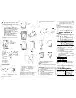
After installation verify the product functionality with the compatible receivers
HSM2HOST9, HS2LCDRF (P)9, HS2ICNRF(P)9, PG9920 and WS900-29,
WS900-19.
Note:
For detailed placement instructions see the alarm systems Installation
Manual.
4. TROUBLESHOOTING
If you encounter one of the following problems with the PGx914, perform
the suggested solution from the following table:
Problem
Solution
Attempt to enroll the sensor is
unsuccessful.
Ensure that the detector is within
wireless communication range of the
receiver. Ensure that the enroll
button on the device is held until the
LED flash is seen, and then
released.
The sensor and the panel do not
communicate.
Perform a placement test as
described in the alarm systems
Installation Manual. Ensure that the
device is within wireless
communication range of the receiver
and remove any possible sources of
interference. If necessary, replace
the sensor's battery.
The sensor sends a low battery
indication.
To ensure continuous proper
operation, replace the battery within
two weeks of the first low battery
indication.
Panel does not arm because of a
sensor malfunction.
Follow the diagnostic test procedure
from Section 3 above to test the
detector. Replace the battery if
flashing LEDs are not seen during
this test. If the system still cannot be
armed, consult with your alarm
system technician for a solution.
5. COMPLIANCE WITH STANDARDS
The PG8914 model complies with the following standards:
Europe: EN 300220, EN 301489, EN 60950-1, EN 50130-4,
EN 50131-1, EN 50131-2-2 Grade 2 Class II, EN 50130-5, EN
50131-6 Type C
UK: The PG8914 model is suitable for use in systems installed
to conform to PD6662:2010 at Grade 2 and environmental
CLASS II. DD243 and BS8243 Certified by Applica Test &
Certification AS in accordance with EN 50131-2-2, EN 50131-
5-3, EN 50131-6, EN 50130-4, EN 50130-5
Applica T & C has certified only the 868 MHz variant of this
product.
The PG4914 and PG8914 models are compatible with the
RED Directive 2014/53/EU of the European Parliament and
of the Council of 16 April 2014
UL/ULC Notes
Only model PG9914 operating in the frequency band 912-
919MHz is UL/cUL listed. The PG9914 has been listed by UL
for commercial and residential burglary applications and by
ULC for residential burglary applications in accordance with the
requirements in the Standards UL 639 and ULC-S306 for
Intrusion Detection Units.
For UL/cUL installations use this device only in conjunction with
compatible DSC wireless receivers: HSM2HOST9, HS2LCD
HS2ICNRF(P)9, PG9920 and WS900-29, WS900-19. After
installation verify the product functionality in conjunction with
the compatible receiver used.
This device complies with Part 15 of the FCC Rules and RSS-247 of ISED.
Operation is subject to the following two conditions: (1) This device may not
cause harmful interference, and (2) this device must accept any interference
received, including interference that may cause undesired operation.
Le présent appareil est conforme aux CNR d'ISED applicables aux appareils
radio exempts de licence. L'exploitation est autorisée aux deux conditions
suivantes : (1) l'appareil ne doit pas produire de brouillage, et (2) l'utilisateur
de l'appareil doit accepter tout brouillage radioélectrique subi, même si le
brouillage est susceptible d'en compromettre le fonctionnement.
WARNING!
Changes or modifications to this unit not expressly approved
by the party responsible for compliance could void the user’s authority to
operate the equipment.
To comply with FCC and IC RF exposure compliance requirements, the
device should be located at a distance of at least 20 cm from all persons
during normal operation. The antennas used for this product must not be
co-located or operated in conjunction with any other antenna or
transmitter.
Le dispositif doit être placé à une distance d'au moins 20 cm à partir de
toutes les personnes au cours de son fonctionnement normal. Les
antennes utilisées pour ce produit ne doivent pas être situés ou exploités
conjointement avec une autre antenne ou transmetteur.
NOTE: This equipment has been tested and found to comply with the limits
for a Class B digital device, pursuant to part 15 of the FCC Rules. These
limits are designed to provide reasonable protection against harmful
interference in a residential installation. This equipment generates, uses and
can radiate radio frequency energy and, if not installed and used in
accordance with the instructions, may cause harmful interference to radio
communications. However, there is no guarantee that interference will not
occur in a particular installation. If this equipment does cause harmful
interference to radio or television reception, which can be determined by
turning the equipment off and on, the user is encouraged to try to correct
the interference by one or more of the following measures:
-Reorient or relocate the receiving antenna.
-Increase the separation between the equipment and receiver.
-Connect the equipment into an outlet on a circuit different from that to
which the receiver is connected.
-Consult the dealer or an experienced radio/TV technician for help.
Cet équipement a été testé et jugé conforme aux limites s’appliquant à un
appareil numérique de classe B, conformément à la Partie 15 des
réglementations de la FCC. Ces limites ont été élaborées pour offrir une
protection raisonnable contre les interferences nuisibles dans une installation
résidentille.
Cet équipement génère, utilize et peut émettre de l’énergie de fréquence
radio et, s’il n’est pas installé et utilize conformément aux instructions du
fabricant, peut provoquer des interférences dangereuses pour les
communications radio. Toutefois, rien ne garantit l’absence d’interférences
dans une installation particuliére. Si cet équipement provoque des
interférences nuisibles au niveau de la réception radio ou television, ce qui
peut étre determine par la mise hors, puis sous tension de l’équipment, vous
étes invite à essayer de corriger les interferences en pregnant les mesures
suivantes:
• Réorientez ou déplaces l’antenne réceptrice.
• Augmentez la distance qui sépare l’équipement et le récepteur.
• Branchez l’équipement à une prise d’un circuit different de celui auquel est
branché le récepteur.
• Consultez le revendeur ou un technician radio/television expérimenté pour
obtenir de l’aide
W.E.E.E. Product Recycling Declaration
For information regarding the recycling of this product you must
contact the company from which you originally purchased it. If
you are discarding this product and not returning it for repair then
you must ensure that it is returned as identified by your supplier.
This product is not to be thrown away with everyday waste.
Directive 2002/96/EC Waste Electrical and Electronic Equipment.
6. Special Comments
Even the most sophisticated detectors can sometimes be defeated or may
fail to warn because of DC power failure or improper connection, malicious
masking of the lens, tampering with the optical system, decreased sensitivity
in ambient temperatures close to that of the human body and unexpected
failure of a component part.
The above list includes the most common reasons for failure to detect
intrusion, but is by no means comprehensive. It is recommended that the
detector and the entire alarm system be checked weekly, to ensure proper
performance.
An alarm system must not be regarded as a substitute for insurance.
Property owners or renters should be prudent to continue insuring their
property, even though they are protected by an alarm system.
SPECIFICATIONS
Detector Type
Dual element low-noise pyroelectric
sensor.
Lens Data
Fresnel and cylinder type
lens with optical
attenuation (PET mask) in
the lower pattern part of
the lens.
Number of beams /
curtains: 27 Fresnel far,
18 cylinder “mid” and 10
cylinder “close”.
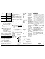
Figure 12 – Coverage
Pattern Walk Test
Max. coverage
12 x 12 m (39 x 39 ft) / 90°.
Pet Immunity
Up to 38 kg (85 lb).
Power Supply
The power supply is type C in accordance
with EN 50131-6 Documentation – Clause
6.
Internal Battery
3V Lithium battery, type CR-123A. For UL
installations, use Panasonic and GP
Wireless only.
Nominal Battery
Capacity
1450 mAh.
Battery Life (for typical
use)
6 to 8 years, (not verified by UL).
Low Battery Threshold
2.4 V.
Note:
Inability to connect with a wireless network,
or low signal strength can significantly
reduce the expected battery life.
Battery Power Test
Performed immediately upon battery
insertion and periodically every several
hours.
True Motion Event
Verification
2 remote sensitivity selections at panel –
LOW or HIGH.
Alarm Period
2 seconds.
LED Switch
LED Enable (red LED lights for 2 sec.
upon alarm detection).
Frequency
Europe and rest of world: 433-434, 868-
869 .
North and Latin America: 912-919.
Note:
Only devices in frequency band 912-
919 MHz are UL/ULC listed.
Communication Protocol
PowerG.
Supervision
Signaling at 4-min. intervals.
Tamper Alert
Reported when a tamper event occurs
and in any subsequent message, until the
tamper switch is restored.
Height
1.8-2.4 m (6 - 8 ft.). For pet immunity, the
optimal height is 2.1 m (7 ft.). At 2.4 m
(7.87 ft.) height installation, remove the
pet mask as pet immunity is not supported
at this height.
Installation Options
Surface or corner.
RF Immunity
20 V/m up to 1000 MHz, 10 V/m up to
2700 MHz (not evaluated by UL).
Operating Temperatures
-10°C to 50°C (14°F to 122°F).
Note: UL only verified operation over the
range 0°C to 49°C.
Storage Temperatures
-20°C to 60°C (-4°F to 140°F).
Humidity
Average relative humidity of up to
approximately 75% non-condensing. For
30 days per year the relative humidity may
vary between 85% and 95% non-
condensing.
For UL installations: 5 % to 93 % non-
condensing. For Indoor use only.
Size (H x W x D)
83 x 61 x 42 mm (3.27 x 2.4 x 1.66").
Weight (with battery)
90 g (3.17 oz).
Color
White.
PATENTS
U.S. Patents 5,693,943 ● 6,211,522 .
COMPATIBLE RECEIVERS
Bandwidth in
MHz
Receivers
433 MHz
HSM2HOST4; HS2LCDRF(P)4; HS2ICNRF(P)4;
PG4920; WS901-14EU; WS901-24
868 MHz
HSM2HOST8; HS2LCDRF(P)8; HS2ICNRF(P)8;
PG8920; WS901-18EU; WS901-28; WP8010;
WP8030
912-919 MHz
HSM2HOST9; HS2LCDRF(P)9; HS2ICNRF(P)9;
PG9920; WS900-29; WS900-19
Note:
Only devices operating in band 912-919 MHz are UL/ULC listed.
Limited Warranty
Digital Security Controls warrants that for a period of 12 months from the date of purchase, the
product shall be free of defects in materials and workmanship under normal use and that in
fulfillment of any breach of such warranty, Digital Security Controls shall, at its option, repair or
replace the defective equipment upon return of the equipment to its repair depot. This warranty
applies only to defects in parts and workmanship and not to damage incurred in shipping or
handling, or damage due to causes beyond the control of Digital Security Controls such as
lightning, excessive voltage, mechanical shock, water damage, or damage arising out of abuse,
alteration or improper application of the equipment.
The foregoing warranty shall apply only to the original buyer, and is and shall be in lieu of any
and all other warranties, whether expressed or implied and of all other obligations or liabilities
on the part of Digital Security Controls. Digital Security Controls neither assumes, nor
authorizes any other person purporting to act on its behalf to modify or to change this warranty,
nor to assume for it any other warranty or liability concerning this product.
In no event shall Digital Security Controls be liable for any direct, indirect or consequential
damages, loss of anticipated profits, loss of time or any other losses incurred by the buyer in
connection with the purchase, installation or operation or failure of this product.
Motion detectors can only detect motion within the designated areas as shown in their
respective installation instructions. They cannot discriminate between intruders and intended
occupants. Motion detectors do not provide volumetric area protection. They have multiple
beams of detection and motion can only be detected in unobstructed areas covered by these
beams. They cannot detect motion which occurs behind walls, ceilings, floor, closed doors,
glass partitions, glass doors or windows. Any type of tampering whether intentional or
unintentional such as masking, painting, or spraying of any material on the lenses, mirrors,
windows or any other part of the detection system will impair its proper operation.
Passive infrared motion detectors operate by sensing changes in temperature. However their
effectiveness can be reduced when the ambient temperature rises near or above body
temperature or if there are intentional or unintentional sources of heat in or near the detection
area. Some of these heat sources could be heaters, radiators, stoves, barbeques, fireplaces,
sunlight, steam vents, lighting and so on.
WARNING: Digital Security Controls
recommends that the
entire
system be completely tested on a regular basis. However, despite
frequent testing, and due to, but not limited to, criminal tampering
or electrical disruption, it is possible for this product to fail to
perform as expected.
Important Information:
Changes
or
modifications
not
expressly
approved by
Digital
Security
Controls
could
void
the
user’s
authority to operate this equipment.
© 2017 Tyco Security Products. All Rights Reserved. www.dsc.com
The trademarks, logos, and service marks displayed on this document are
registered in the United States [or other countries]. Any misuse of the
trademarks is strictly prohibited and Tyco will aggressively enforce its
intellectual property rights to the fullest extent of the law, including pursuit of
criminal prosecution wherever necessary. All trademarks not owned by Tyco
are the property of their respective owners, and are used with permission or
allowed under applicable laws. Product offerings and specifications are
subject to change without notice. Actual products may vary from photos. Not
all products include all features.
Availability varies by region; contact your sales representative.
Tech Support: 1-800-387-3630 (Canada & U.S.) or+800-2255-8926
Printed in Israel • www.dsc.com
D-306633 PGx914 Installation Instructions
2

