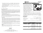
Level of Detection (Jumper J2)
The AMA-100 glass break detector comes with a “detection level” jumper setting
(Jumper J2), which allows the selection of one of two levels of detection,
depending on the size and acoustics of the room in which the detector will be
installed. This improves the overall false alarm immunity of the detector.
The detector is factory preset for Level 1 detection (Jumper J2=OFF). This is the
highest sensitivity setting of the detector, and is designed for applications
requiring high sensitivity and range, such as larger rooms, or rooms which
contain a significant amount of sound-absorbing surfaces (such as carpets,
furniture, drapes, etc.). Level 1 will be suitable for most applications.
For rooms which are smaller, and contain a significant amount of hard, sound-
reflective surfaces (such as kitchens, bathrooms, entrances etc.), Level 2
detection (Jumper J2=ON) provides a lower sensitivity setting which is more
appropriate for these environments.
NOTE: Jumper J1 is not used and must always be left on.
Locating The Detector
NOTE: Test the detector thoroughly for proper placement using the AFT-100
Glass Break Simulator. Other simulators may trip the unit, but will not
provide accurate indications.
• For optimum protection, the detector should have a direct line of sight to the
protected glass.
• Window coverings will absorb sound energy from the shattering glass. In these
cases, mount the detector as close as possible to the protected glass, either
on an adjacent wall, the ceiling, or behind the window covering if possible.
• The detector should be mounted at least 1.8m (6 feet) off the ground.
• Do not mount the detector on the same wall as the protected glass. Refer to the
diagram below for correct and incorrect mounting locations.
• Avoid installation near “noisy” sources, such as speakers or other objects
which produce sounds continuously.
• Do not install the detector beyond the maximum recommended range, even if
the AFT-100 simulator shows additional range - future changes in room
acoustics could reduce that additional range.
• Application on 24 hour loops should be avoided unless the location is
unoccupied.
• Test false alarm immunity by creating any sounds in the room which will likely
occur when the alarm system is armed.
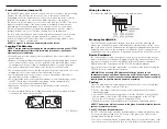
D = Distance
Wiring the Device
To connect the AMA-100, consult the wiring diagram below:
Mounting the AMA-100
Once the location has been determined, open the detector by pressing the
release tab on the bottom with a small flat-blade screwdriver. Remove the cover
and set in a safe location. Draw the wires through the rectangular opening in the
backplate and connect to the terminal block. Mount the detector using the two
mounting screws. Once the device is wired and mounted, you will need to enroll it.
Device Enrollment
The serial number located on the back of the device must be enrolled into the
alarm control panel via Installer’s Programming ([
✱
] [8] [Installer’s Code]). This
procedure is outlined for the PC4010/4020 in the control panel Installation
Manual and for the Power panels in the PC5100 Installation Manual.
Once the detector is enrolled, replace the cover and test the detector using the
AFT-100 tester to confirm proper operation.
WARNING: Connect only DSC Addressable Series devices to the
addressable loop connections. Connection of ANY other type of device will
impair operation. Any devices other than Addressable Series devices which
require power to operate must be powered separately.
Testing
Once you have mounted, wired and enrolled the detector, test to ensure that
the detector is working correctly. To do this:
1. Put the control panel in walk test mode as described in the control panel
installation manual.
2. Use the AFT-100 glass break simulator to test the AMA-100. When the AMA-
100 is working correctly, the LED will light up in response to the AFT-100.
Refer to the section below for tips on using the AFT-100.
3. End walk test mode as described in the control panel installation manual.
NOTE: The detector will not respond to the glass break simulator unless the
system is in walk test mode.
The AFT-100 Glass Break Simulator
The AFT-100 glass break simulator generates plate or tempered glass samples.
Use the plate glass setting if you are unsure of the glass type. Observe the
following when testing the detector:
• The correct mounting location is indicated by three successive detections. If the
detector does not respond each time, relocate the detector and repeat the test.


