background image


The noise level this machine generates at the operators’ position is less than 70dB. 

Keep  this  manual  near  the  machine  for  future  reference.  Also  check  our  website  for  any 

additional or updated safety information.  (www.drytac.com) 


Installation/Training is also available for your 

JetMounter

.   This service assures that your new 

laminator  is  set  up  properly  and  the  operators  are  trained  in  the  various  applications  the 

equipment can perform.   Contact our Customer Service Department for details or if you have 

any  questions  about  the  operation  of  this  equipment  or  would  like  to  make  arrangements  for 

such a session.  

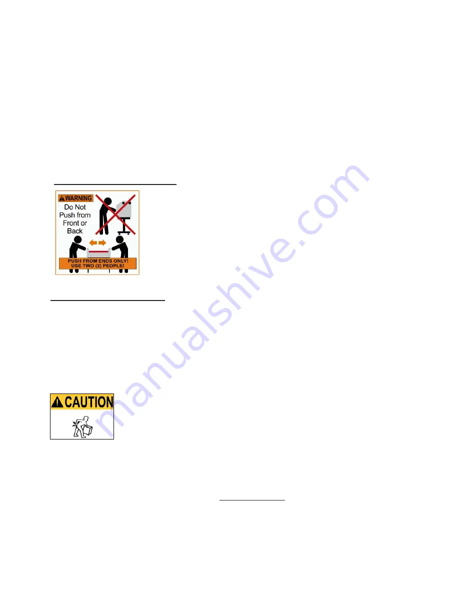
Specific Moving Instructions 


The Drytac JetMounter

TM

 is to be handled with care to avoid personal 

injury  or  collateral  damage.    Whenever  the  machine  is  moved,  we 

strongly recommend utilizing at least two people.  The adage: “Better 

safe  than  sorry,”  applies  here.    When  moving  the  machine,  the 

movers  should  be  positioned  at  both  sides.    Do  not  push  the 

JetMounter

TM

 from the front or back!  This eliminates the possibility 

of having the machine tip over onto the mover or their helper.  

Unpacking and Installation  

Upon  receipt  of  your  new  JetMounter

,  inspect  the  carton(s)  carefully  for  signs  of  physical 

damage  or  mishandling.    There  are  two  rough  handling  indicators  that  should  be  inspected 

before the shipment is signed for.  If either of the devices is “tripped”, this must be noted on the 

receiving  paperwork.  Report  any  damage  to  the  shipping  company  immediately  and  contact 

Drytac  Corporation  if  replacement  parts  are  needed.    If  there  is  no  apparent  damage,  proceed 

with unpacking.


It  is  recommended  that  at  least  two  people  unpack  the  JM  Pro  XD  to  avoid 

damage to the equipment or personal injury.  Follow the instructions attached 

to  the  front  of  the  crate  to  remove  the  laminator  correctly  and  safely.    If  the 

instructions  are  missing  check  the  appendix  in  this  manual  for  an  illustrated 

version or contact Drytac Technical Services before attempting to unpack or install the machine. 

Also see appendix for heating element installation procedure.  If there are any questions about 

electrical  requirements  for  the  equipment,  please  contact  a  qualified  electrician  prior  to 

attempting  to  power  up  the  machine!    Be  absolutely  certain  that  the  voltage  supplied  at  the 

outlet corresponds with the voltage marked on the plate attached to your machine.  Do not rely 

on the cord or outlet configuration to determine the correct power supply voltage!   

Summary of Contents for JetMounter Pro

Page 1: ...OPERATOR S MANUAL 9 16 16 ...

Page 2: ...without notice and should not be construed as a commitment by Drytac Corporation Drytac Corporation assumes no responsibility for any errors that may appear in this document Nor does it make expressed or implied warranty of any kind with regard to this material including but not limited to the implied warranties of merchantability and fitness for a particular purpose Drytac Corporation shall not b...

Page 3: ...phics onto cardstock foam board MDF or rigid PVC board Equipped with the performance features our customers demand JetMounter ProXD wide format models are unmatched for value JM Pro XD Features Heavy Duty One Piece Durable Metal Construction Interchangeable Large Diameter 5 5 139 7 mm Silicone Non Stick Rollers Fully Heated Upper Roller with F C Display Capability 248 F 120 C Drytac s Heavy Duty S...

Page 4: ...g a Graphic to a Pre Coated Board 14 Laminating with the JetMounter Laminators Selecting a Laminate Film 15 Single Unmounted Image 15 Single Mounted Image 16 Laminating Multiple Mounted Images 17 Using a Leader Board Carrier Boards and Preparing Mounting Boards 18 Care and Maintenance 19 Technical Specifications and Contact Information 20 Registration Information and Warranty 21 Appendix Operation...

Page 5: ...led the Nip This area creates a potential pinch hazard for fingers or other objects DO NOT OPERATE THIS EQUIPMENT IF YOU ARE UNWILLING TO ACCEPT THIS HAZARD TO AVOID INJURY ALWAYS KEEP YOUR FINGERS AWAY FROM THE NIP AREA No persons under the age of 16 should be allowed to operate the equipment The following safety features are designed to offer a reasonable measure of protection against injury whi...

Page 6: ...nt Keep loose clothing neckties artificial fingernails long hair and anything else that might easily be drawn into the rollers away from the machine Turn the JetMounter power OFF if you are loading adhesives or film cleaning the rollers or performing other activities that require close proximity of your fingers to the Nip This will avoid the possibility of inadvertently starting the machine Keep y...

Page 7: ...on receipt of your new JetMounter inspect the carton s carefully for signs of physical damage or mishandling There are two rough handling indicators that should be inspected before the shipment is signed for If either of the devices is tripped this must be noted on the receiving paperwork Report any damage to the shipping company immediately and contact Drytac Corporation if replacement parts are ...

Page 8: ...switch is a Breaker located on the back of the left end case of the machine near the power cord entry This switch should be in the OFF position when loading or unloading adhesives or film cleaning the rollers or performing other activities that require close proximity of your fingers to the Nip Use this breaker to power down after processing is completed for each day 2 The Control Panel Power Pad ...

Page 9: ...ONTROL located to the right of the ROLLER FWD REV Buttons is used to control the speed of the motor driven bottom roller Rotating the knob to the right or left will increase and or decrease the speed of the roller The speed control will not affect the reverse speed or the speed of the roller when the photo cell beam is interrupted while processing with the use of the Foot Pedal In that circumstanc...

Page 10: ...ximum spring compression is restricted The Hand Wheel is located on the front of the right end case Simply turn the hand wheel to raise or lower the top roller The Supply Shaft holds the adhesive or laminate material while the Take Up or wind up Shaft holds the release liner The two shafts below the table level can be used as either supply or take up as the application calls for When any of the sh...

Page 11: ...tMounter Pro XD is equipped with a motorized Take Up shaft on the upper front of the machine This shaft winds up the release liner from the mounting adhesive and overlaminating film rolls during processing Also on these models both the Take Up Shafts and the Supply Shafts are equipped with Tension Control Knobs It is important to adjust these settings so that there is an even tension on the adhesi...

Page 12: ... image can be mounted to the board later The use of a Leader Board is recommended for this process 1 Adjust rollers for proper pressure 2 Load the roll of PSA pressure sensitive adhesive onto the Supply shaft so that the material can be pulled toward the user from the underside of the roll with the adhesive side facing UP the release liner side should be in contact with the roller as shown in the ...

Page 13: ... going to be laminated with a gloss overlaminating film the use of very smooth substrates with glossy surfaces such as Masonite is preferred This will minimize the effect of board imperfections i e orange peel in the finished product NOTE We recommend placing a Tail Board behind the last production board this can be the same board used as a leader board starting panel This is especially important ...

Page 14: ...ine 5 Square your mounting board with the tacked print against the edge of the Leader Board and drape the print over the top roller 6 Run the mounting board adhesive image through the rollers while simultaneously pulling the release liner away from and off of the board JM Fuzion XD has three automatic Take Up shafts on the front and lower rear of the chassis You may choose to unwind the Release Li...

Page 15: ...mmended for this purpose 1 Raise the top roller and insert the Carrier Board Set roller pressure as described in previous chapter 2 Pre cut a sheet of overlaminating film from the roll The sheet should be larger than the image by approximately 1 on each side and bottom and 2 on the top 3 Peel and fold back approximately 2 of release liner from the top edge of the overlaminating film Tack the film ...

Page 16: ... do not stop until the entire image has passed through the rollers 7 The laminated image can now be easily removed from the silicone coated Carrier Board for trimming and mounting Laminating a Single Mounted Image Before processing make sure that the images are clean and free of dust or specks of lint an Anti Static cloth or Anti Static Wisk is recommended for this purpose 1 Raise the top roller a...

Page 17: ...d back release paper with one hand start the rollers and apply the laminating film to the surface of the image Pull up and away on the release liner as you advance to ensure that the liner does not reach the Nip area Process your work with a consistent motion and do not stop until the entire image has passed through the rollers 9 Trim excess overlaminating film from the edges of the image Laminati...

Page 18: ... production mounting board and about 6 8 long You should also make a Tail Board which is used behind the last production board The Tail Board is especially recommended for mounting to foam board Carrier Boards When processing un mounted images we recommend you use a silicone coated board to prevent adhesives from sticking to the rollers This board is called a Carrier Board and it provides a re usa...

Page 19: ...es are 5 x 20mm 5 Amp The use of any fuse without the same rating specified may endanger the operator and or machine and invalidate the warranty Spare fuses can be found inside the schematics envelope located inside the left end panel Lubrication Lubricate the drive and take up chains located inside the right end case every six months with a premium brand chain lubricant Inspection and Lubrication...

Page 20: ...m Max Laminating Width 63 160 cm Max Material Diameter 10 25 4 cm Electrical Requirements 220V 50 60Hz 3580 Watts Speed Range 1 20 fpm 0 5 6 mpm Core Size 3 7 6 cm Packaged For Shipment Height Weight 60 152 cm 1094 lbs 496 kg Width 90 229 cm Depth 28 71 cm CONTACT INFORMATION Drytac Corporation USA Drytac Europe UK 5601 Eastport Blvd Filwood Road Fishponds Richmond VA 23231 Bristol BS16 3RY United...

Page 21: ...xpired Drytac will provide all reasonable assistance and product support to resolve any problems that may arise Please return your warranty card as soon as possible This will help us more efficiently assist with any problem you may encounter You will find a section for recording this important information for your records and any future parts or service requests on page 22 of this manual Normal we...

Page 22: ...Control Panel c Roller will not rotate unless the ROLLER pad is pressed on the Control Panel When the footswitch is pressed the rollers will rotate at the set speed When the footswitch is pressed the rollers will continue rotating Speed will slow to 2 fpm When the footswitch is pressed the rollers will rotate at 2 ft min Foot Switch Operation When the footswitch is released the rollers will stop r...

Page 23: ...the machine 4 Inside the box located behind the front feed table on the left side are the necessary wrenches for following steps 5 Locate any items stowed below the machine on the base pallet wooden blocks and the Heating Element box or core and remove them carefully before proceeding 6 Confirm the casters are all pointing away from the Ramp End of the base pallet before proceeding The end that th...

Page 24: ...n either side of the machine and carefully guide the machine off the base pallet down the ramps 11 Remove the shrink wrap from the machine DO NOT use any sharp tools near the rollers Follow the instructions provided in the Operator s Manual to set up and operate your new Pro XD Important The JM 63 Pro XD must be on a level surface in order to operate properly The JM Pro XD requires a single phase ...

Page 25: ...er or other long rigid device can be used to guide the end of the element through the journal With the element in the roller you have access to both the ceramic ends Remove the round silicone insert inside the clamp portion of the bracket Loosen the two clamp screws to make installation easier Carefully fit one silicone sleeve insert over each ceramic end of the element Attach the brackets to each...

Reviews: