


English
IN ST AL LA TI ON M AN U AL
yes
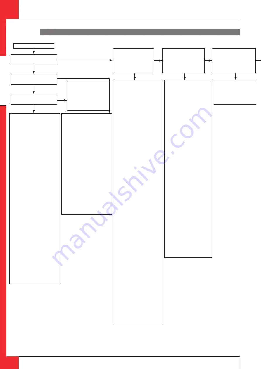
Start
2.01 Can pilot be lit?
2.03 Only one spark?
2.02 Sparking?
2.09
Ignition procedure
- Oval knob on gas control is on
"MAN". Set to "ON" and restart.
Retarded ignition of main
burner(s)
Gas to main burner opens ca. 3-5
seconds after servo motor,
operating the gas valve, starts
running (sound of motor!). After
this the main burner is to ignite (at
least partially) within 10 seconds
and not with a firm noise WHOOF.
If not: no or delayed cross lighting
of main burner.
Hazardous situation.
Stop ignition procedure straight
away and first check for:
- Position of logs or pebbles.
- Burner holes (locally) blocked.
Remove vermiculite dust.
- Vermiculite missing.
- Chips on burner.
- Vermiculite not distributed
evenly across burner(s).
PowerVent® (if present)
Burner does not light. Consult
PowerVent® installation manual
how to carry out the checks below.
Check:
- 230 V to fan controller unit and
fan.
- Silicon pressure measurement
hoses:
- swapped;
- leaking or barred.
- Pressure difference set too high.
- Resistance of flue system too
high:
- adjustment (of appliance
damper and air inlet guides);
- flue length or number of bends
too large;
- dirty (e.g. cobwebs).
- Operation of the fan.
- Operation of solenoid gas valve.
- Operation of fan controller unit.
- Operation of pressure
measurement gauge.
2.11
No proper cross lighting
of main burner(s).
Go to box 2.09 and take
actions act as described for
'retarded ignition of main
burner'.
2.06 Pilot can be lit.
Does it stay alight?
2.10 Do(es) main burner(s)
ignite smoothly and across
its/their full length after first
ignition by pilot burner?
2.08 Does main burner
ignite immediately?
2.04 Check:
Receiver
- Replace missing, weak or
rechargeable batteries (not enough
power to open thermoelectric
valve).
Presence of gas on pilot burner
Check pilot on presence of gas at
normal ignition cycle or in Manual
Mode (turn oval knob on gas control
to MAN and keep safety shut off
valve opened with a screwdriver) and
ignite pilot with a lighter.
- Pilot flame not on: Step 1.
- Pilot flame on: Step 2.
Step 1: Pilot has no gas
Check:
- Gas tap open?
- Gas at gas control (line pressure at
measuring point on gas control).
- Gas flowing out of gas control? (by
loosening pilot tube at gas control).
If not: check adjustment screw pilot
flame (under black cover): sealing
not to be broken.
Sealing broken: screw should be
fully open.
- Blocking of pilot tube (kink or dirt).
- If this does not help: replace gas
control.
Step 2: Pilot has gas, but no
ignition
- Electrode with
90° bended
tip:
bend tip 1 mm higher.
- Spark too weak (thin and reddish).
Act as if 'no spark' in box 2.05 and
perform actions described for
ignition cable and ignition
electrode.
- Pilot flame too weak (dirty).
Remove injector (remove gland nut
and the pilot tube). See that it does
not fall away. Clean with
compressed air.
Rectify. Retry.
2.05 Check:
Ignition cable
- Present and connected.
- Being free from metal parts or
concrete.
- Too long: cut away all excessive
length at receiver end, and
reconnect.
- Shorting out to earth: replace
ignition cable.
- Spark in wrong position:
- slide rubber sleeve on ignition
cable over ceramic of electrode.
- Replace electrode if neccessary.
Ignition electrode
-
Straight
electrode:
- oxidation (roughen electrode
with file or sand paper);
- position (4 mm from pilot burner).
- Cracks in ceramic (not always
visible): replace electrode.
Starting procedure
After switching off/going out the
remote is locked for 120 sec. (older
versions 60 sec).
Wait 2 minutes before reigniting.
2.07
Pilot out when servomotor starts
to run? Check the thermocouple
system.
- Measure thermocouple voltage in
mV just after servomotor starts to
run and the voltage goes down.
- Measure between red dot on
receiver and earth point on gas
control (fig. 42).
- 0 mV
- 2-3 mV
- 3-5 mV
- 6 mV and higher
- Requirement: after rectification
actions thermocouple voltage
should be 6 mV at least, just after
motor starts running!
Voltage 0 mV
- Thermocouple defective. Check by
replacing or measuring voltage at
end whilst heating (tip: with a
lighter).
- Short circuiting or interruptions in
circuit:
Check:
- thermocouple tight in
interruptor;
- interruptor tight in gas control;
- black wires (yellow/red end)
connected to inter
receiver;
- interruptor (mount
thermocouple directly in gas
control and ignite in Manual Mode
(see 2.04).
If pilot stays on: interruptor
defective.
Voltage 2-3 mV
- Check pilot flame.
Too small:
- pilot dirty.
Clean up (see 2.04).
- check for pilot gas tube
tightness;
- pilot tube kinks or dirt inside;
- line pressure too low.
- Tip: thermo couple not in (correct!)
pilot flame.
Bend into flame.
Voltage 3-5 mV
- Appliance may work, but is too
critical.
Perform actions as described for
2-3 mV.
Voltage 6 mV and higher
Voltage OK, so different cause.
- Receiver defective. Check by
dismounting black-red and yellow
control cables from receiver and
link together. Ignite fire in Manual
Mode (see 2.04). Pilot stays on:
receiver defective.
- Gas control defective if receiver is
not defective. Replace gas control.
yes
no
yes
yes
no
no
no
no
no
Fires with electronic ignition, fault finding: Ignition and burning
Appendix 1 diagnosis of malfunctions
GB
20
2.03a
- Loosen and retighten
earthing screw on gas
control.
- If this does not work:
replace receiver.
yes
yes


