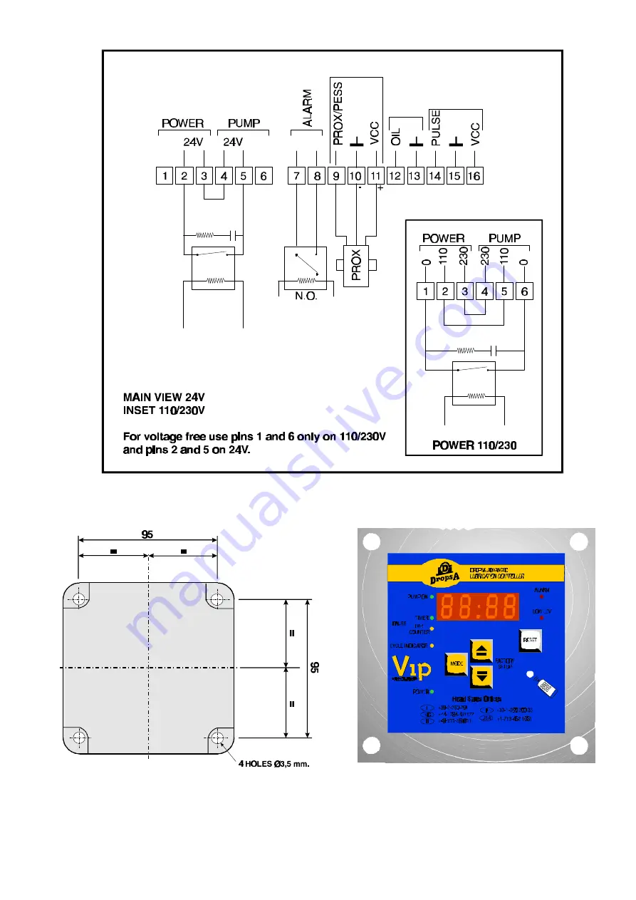
Fig. 1. Connection Details.
Fig. 2. Fixing Details
Fig. 3. Panel Mounted Version.
3
C1019IE-10/97
Page 1: ...considerable time saving for OEM s who use the system on a production line eliminating the need to individually configure each controller 2 SPECIFICATION INPUT CONTACTS Power 110V 230V 24V 220V Single...
Page 2: ...o to the next option Pause Interval Selection The Pause between the Pump ON cycle is determined by a timer The Pause between Pump cycles is determined by the cycle switch input connected to pulse Pres...
Page 3: ...Fig 1 Connection Details Fig 2 Fixing Details Fig 3 Panel Mounted Version 3 C1019IE 10 97...
Page 4: ...lease contact our Technical Office 9 DIAGNOSTIC TABLE ALARM CODES DESCRIPTION OF FAULT ACTION AO1 No parameters set Set parameters AO2 Low Level alarm Add lubricant to the system AO3 The change over c...