background image

drive.web automation

smarty 

Terminal Naming and Ratings

Terminal names are consistent in the 

drive.web savvy

 software and 

on the carrier itself.  

24VDC  and  0V

  Terminals  are  internally  connected. 

Supply regulated 24VDC ±5%, 100mA plus loads, 

to only one pair of  24VDC and 0VDC terminals.   

Do not connect to a distributed DC power network.  

External


1A fast-acting fuse or current-limiting is required!


Supply from Class 2, LPS, limited power supply only. 

AI

 - Analog inputs. -11VDC to +30VDC, 100k

Ω

, 1kHz. 

AO

 - Analog outputs. 

dw241

 is unipolar, ~0.2VDC to 10.5VDC, 

10mA. All others are bipolar, -10.5VDC to +10.5VDC. 

DI

 - Digital inputs. 50VDCmax, 8VDC threshold, 3V hysteresis. 1kHz. 

DO

 - Digital outputs. 24VDC source, up to 350mA, shared. 

Overcurrent protection and software indication. Maximum 

Voltage is 25.2VDC. 

1A+

 - Example: Encoder 1 Channel A+. Differential, incremental, 

quadrature encoder input. 24VDC max, -0.5VDC min., 

0.3VDC minimum differential Voltage. Up to 1MHz. 

FI 

- Frequency/event/digital input. 30Vmax, 100kHz. 

TO

 - Frequency/stepper/digital sinking output. 350mA shared, 

30VDC max., 500kHz max. 10k

Ω

 pull-up to 

TPWR

 (+5VDC 

for 

FT

 terminals and 

C5

C5


TO

 are 5VDC max.). 

Caution! 

TO

 are sinking outputs without internal over-current 

protection. The installing engineer must assess the risk of  

overload and provide external protection to avoid damage to the 

unit, depending on the installation. 

FT

 - Combined 

FI

 and 

TO

, 5VDC max. 

CI

 - Current Input. 100

Ω

 input impedance. Maximum input is 25mA, 2.5VDC. 

TPWR 

- Timing output power source. 30VDC, 350mA max. 

+5V

 Power supply outputs for use with encoders, sensors, and the 

TPWR

 terminal.  


Maximum total current output is 500mA. 

485+

 - Example: ModbusRTU serial port non-inverting pin, ‘B’.

smarty 

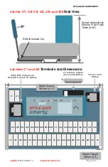
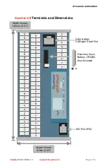
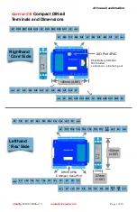
Terminals and Wiring

C1

  thru 

C4


Terminal  wiring

  -  Strip  7mm(0.28”)  or  use 

ferrules.  Use  0.08mm

(AWG28)  minimum.  One  bare 

wire, 2.5mm

(AWG14) max. Two wires, 0.8mm

2

(AWG18) 

max. One wire with ferrule, 1.5mm

(AWG16) maximum. 

C5

 wiring is per contact type. Uses 24-position Molex Mini-Fit 

Jr. Housing 5557.   

C6

  Terminal  Wiring  -  Strip  7mm(0.28”).  1.5mm

(AWG16) 

maximum. 

Use shielded cable for runs over 30 meters. 

Fast transient over-Voltage 1kV per EN 61000-4-4.

smarty


HG503894Iss2.0


www.driveweb.com


Page  /16

3

Summary of Contents for smarty dw24 Series

Page 1: ...ding interference that may cause undesired operation This Class A digital apparatus is designed to comply with Canadian ICES 003 Cet appareil numerique de la classe A est conforme la norme NMB 003 du...

Page 2: ...G IN ANY WAY OUT OF THE USE OF THIS SOFTWARE EVEN IF ADVISED OF THE POSSIBILITY OF SUCH DAMAGE Product Identification smarty The smarty dw24X Series Universal Automation Controllers UAC consist of a C...

Page 3: ...TO Frequency stepper digital sinking output 350mA shared 30VDC max 500kHz max 10k pull up to TPWR 5VDC for FT terminals and C5 C5 TO are 5VDC max Caution TO are sinking outputs without internal over c...

Page 4: ...urce DIN rail mounting Use 35x7 5mm rail per IEC 60715 or EN50022 Environment UL IEC Pollution Degree 2 Operating temperature 0 C min 50 C max Storage temperature 20 C to 60 C Altitude 3000m max Humid...

Page 5: ...input ModbusRTU serial port is brought out to terminals instead of the jack in C2 smarty C4 Carrier 4 adds to C3 Two 4 20mA current inputs Also 0 20mA 20 4mA and 20 0mA 100 input impedance Six freque...

Page 6: ...7 DO1 DO3 DO5 DO7 0V A01 AO3 AO5 AO7 AI1 AI3 AI5 AI7 0V 24V DI2 DI4 DI6 DI8 DO2 DO4 DO6 DO8 0V A02 AO4 AO6 AO8 AI2 AI4 AI6 AI8 0V 24V Clock Battery CR2032 Not included C2 Only XIO Port 4P4C C2 Only DR...

Page 7: ...AI5 AI7 0V 0V 1A 1B 0V 0V FT1 FT3 24V DI2 DI4 DI6 DI8 DO2 DO4 DO6 DO8 0V A02 AO4 AO6 AO8 AI2 AI4 AI6 AI8 0V 5V 1A 1B 0V 5V FT2 FT4 0V 0V 0V 0V 0V 24V 0V A B Carrier C3 Terminals and Dimensions XIO Por...

Page 8: ...TO2 TO4 TO6 24V DI2 DI4 DI6 DI8 DO2 DO4 DO6 DO8 0V A02 AO4 AO6 AO8 AI2 AI4 AI6 AI8 0V 5V 1A 1B 1Z 0V 5V 2A 2B 2Z 0V CI2 5V FI2 FI4 FI6 5V 24V TO1 TO3 TO5 TO7 0V 0V 0V 0V 0V 0V 0V 24V 0V 24V 0V A B 0V...

Page 9: ...y CR2032 Not included XIO Port 4P4C 63mm 2 48 57mm 2 24 J7 J8 J9 DRIVE XIO 1 2 3 4 5 6 7 8 9 10 11 12 13 14 15 16 17 18 19 20 21 22 23 24 1 2 3 4 5 6 7 8 9 10 11 12 13 14 15 16 17 18 19 20 21 22 23 24...

Page 10: ...FI3 FI4 FI5 FI6 485 A 485 B 0V 24V 0V 5V 1A 1A 1B 1B 1Z 1Z 0V CI1 0V Lefthand Flex Side DRIVE 8P8C CANopen Serial Port 104mm 4 09 27mm 1 06 0V DO8 DO7 DO6 DO5 0V DO4 DO3 DO2 DO1 0V 24V 0V DI8 DI7 DI6...

Page 11: ...utputs for use with motion control function blocks FI Frequency Inputs Useful for lower frequencies 10kHz Duty cycle is also measured Updates every FBE cycle or two edge cycle smarty XIO Digital IO Mo...

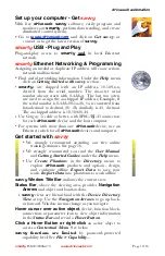
Page 12: ...for each drive web device and the host computer For systems with more than one drive web device use an Ethernet switch for all drive web devices and computer Get started with savvy We strongly recomm...

Page 13: ...Icon Contextual Menu Change Name Name your smarty for easy identification Import Export Device Data Load save configuration data to from this smarty only Unlock Lock Set Password Choose Restrict Modif...

Page 14: ...execution order from top down Change execution order by dragging function blocks up or down the list In this picture ENC1 Speed function block is moved so that it is processed after ENC Phase Lock sav...

Page 15: ...in Java based savvyPanel Appears as graphic tile in iOS Function blocks enable savvyPanel actions Alarm Annunciator Provides a system wide alarm annunciation when active Touch to view page 255 Presenc...

Page 16: ...read only or have incoming drive web connections Click the Comms Server icon in the FBE or SFD view dwOption 04 ModbusTCP IP slave server Supported Modbus Function Codes 1 thru 6 15 and 16 Supports u...

Reviews: