background image

9

FOOTREST

Your Cirrus Plus wheelchair comes standard with swing-away detachable footrests and
foot-plates, which are height adjustable. To adjust the height, remove the (Fig. 14)
securing screws and nuts from each side and slide the extension tube and footplate up
or down to the desired height. 

WARNING! Never lift the wheelchair by the footrests. These parts are detachable and will
not bear the weight of this chair. Lift this chair ONLY by non-detachable parts of the main
frame. Never use the footrest to open doors. 

Bolts

Fig. 14

Summary of Contents for Cirrus Plus

Page 1: ...12 Harbor Park Drive Port Washington NY 11050 Toll Free 877 224 0946 516 998 4600 Website www drivemedical com OWNERS MANUAL INSTRUCTIONS ...

Page 2: ...1 Armrest Rear Wheel Set Casters Fork Footrests Frame Controller Batteries Back Upholstery ...

Page 3: ...n order to prevent loss of steering control or the possibility of tipping over backwards an attendant is recommended when going up inclines greater than 6 If it becomes necessary to stop when going up an incline special care must be taken to avoid abrupt or sudden forward movement when you resume operating the chair to avoid tipping the chair backwards Always keep the chair under control when goin...

Page 4: ...y footrests Fig 1 3 Rear drive wheels Fig 2 4 Anti tip wheel Fig 3 5 2 Batteries Rechargeable sealed lead acid battery U1 35 Amp Seperate Boxes 6 Battery Tray Fig 4 7 Battery Charger 4 amps 8 Controller P G VSI SO Fig 15 9 Motors 24VDC Fig 2 ASSEMBLY Assemble the main parts mentioned as per the following procedure and check the assembly for normal operation 1 Mount the swing away footrests 2 Drive...

Page 5: ...e plugs and ensure that the power cables are clear of obstacles when replacing the battery box lid Tighten the battery box securing strap Fig 15 2 Place batteries into battery boxes Insert the battery box with the external power connection towards the front of the chair 3 Slide the power control module into the mounting bracket under the armrest and secure it into position Your control module can ...

Page 6: ...n then be put in place on the back of the seat posts TO FOLD THE WHEELCHAIR FOR STORAGE OR TRANSPORTATION 1 Fold up the footplates and unlock the levers which position the footrests Swing the footplates and leg rests away Either leave the foot plates in this position Fig 8 or remove them completely by lifting each leg rest vertically to clear the front hangers 2 Remove the Batteries from the Batte...

Page 7: ... presence of an attendant DO NOT disengage the drive motors when your wheelchair is on an incline The chair could roll down on its own causing injury To engage or disengage the freewheel feature 1 Turn the freewheel levers outward to disengage the drive motors 2 Turn the free wheel levers inward to engage the drive motors NOTE It is important to remember that when your Cirrus Plus Wheelchair is in...

Page 8: ... lever found beside the support tube and remove it from the locating hole The controller unit can easily be adjusted to different positions in order to meet user s demand To adjust it Fig 12 loosen the knob and move the mounting tube to the desired position then tighten the screws The armrests can be unlocked and pivoted to the rear of the chair frame to assist in patient transfers The width of th...

Page 9: ...Cirrus Plus wheelchairs feature seat upholstery that can be tensioned While there should be no adjustment necessary upon delivery of your new chair over time stretch of the upholstery could occur Contact your dealer for adjustment WARNING REPLACE WORN OR TORN FABRIC IMMEDIATELY FAILURE TO DO SO MAY CAUSE SEVERE INJURY Fig 13 ...

Page 10: ...e the Fig 14 securing screws and nuts from each side and slide the extension tube and footplate up or down to the desired height WARNING Never lift the wheelchair by the footrests These parts are detachable and will not bear the weight of this chair Lift this chair ONLY by non detachable parts of the main frame Never use the footrest to open doors Bolts Fig 14 ...

Page 11: ...air to SLOW 2 Press the on off switch 3 Push the joystick gently in the direction you whish to travel applying a steady even pressure The further you push the joystick the faster the chair will go The chair will stop when you return the joystick to the neutral or vertical position 4 Directional control is achieved by gently moving the joystick in the direction you wish to go Pull back to reverse 5...

Page 12: ...erating the Cirrus Plus Wheelchair If operating your chair on the roads please check with your local transportation law enforcement regarding necessary identification and safety devices such as reflectors CHAIR OPERATION ON SURFACES THAT REQUIRE SPECIAL CARE When driving up or down ramps it is recommended that the user 1 Visually checks to see if the angle of the slope is less than 6 2 Checks to s...

Page 13: ...is greater than 1 1 2 it is not recommended that the user climb or descend the curb Should there be any doubt an assistant should be called to supervise the operation STEEP SLOPES When the power wheelchair is to be operated up and down steep slopes it is recommended that the user 1 Visually checks to see if the angle of the slope is less than 6 degrees 2 Checks that the slope surface is roughened ...

Page 14: ...ediate area 4 Turn the chair controller power off before charging 5 It is advisable that the batteries be charged for a minimum of 8 hours or over night to ensure a full return to the batteries storage capacity The battery charger is an automatic current limiting device and will shut off when the batteries are fully charged 6 Position the Cirrus Plus wheelchair next to a standard wall outlet 7 Con...

Page 15: ... battery box and remove the battery as in step 7 Undo the terminal lugs noting the polarity of the lugs Remove the wiring loom 8 Repeat step 6 for the other battery 9 Inspect the terminals on the wiring loom and the lugs on the replacement batteries to make sure they are clean 10 Connect the terminal lugs on the wiring loom to the new batteries observing the polarity of the lugs as noted before 11...

Page 16: ...15 BATTERY CONNECTIONS BLACK RED CUT OUT SWITCH RED CONNECTOR RED BLACK RED BLACK FRONT Fig 16 ...

Page 17: ...eel screw from the center hub of the wheel 2 Pull the wheel off of the axle 3 Separate the tire from the rim Pneumatic style only 4 Remove the tire and replace it with a new tire Pneumatic style only 5 Slide the wheel back onto the shaft 6 Install the drive wheel nut into the center hub and tighten TIRES ...

Page 18: ... power chair is functioning properly and helps prevent future complications This should include 1 Checking the tires 2 Checking the batteries and terminals 3 Checking the controller programming for the user s needs 4 Checking the wheelchair frame 5 Checking the upholstery condition REGULAR MAINTENANCE AND CLEANING 1 Avoid knocking or bumping the controller and the joystick 2 Avoid prolonged exposu...

Page 19: ... joystick for damage Visually inspect the boot Do not handle or try to repair it See authorized dealer if there is any problem 12 Visually inspect the controller harnesses Make sure that they are not frayed or cut or have any wires exposed See authorized dealers if there is a problem with any of these harnesses 13 Ensure that all parts of the controller system are securely fastened to your Power w...

Page 20: ... all the leads have been properly connected and the main power is turned on If this doesn t cause the red light on the charger to illuminate turn the main power off disconnect the lead from the main to the battery charger Contact your Dealer and advise of the problem PROBLEM The chair is difficult to steer ACTION First check the tires are in proper positions Second check to see if both the clutche...

Page 21: ...es Motor brushes are wear items and are not warranted The chair side frames are guaranteed for a period of FIVE YEARS from date of purchase WARRANTY EXCLUSIONS Batteries Tire Upholstery and seating Repairs and or modifications made to any part without specific prior Written from DRIVE Medical Design Manufacturing Labor service calls shipping and other charges incurred for repair of the product unl...

Page 22: ...ted with the freight of the chair or any faulty components are the responsibility of the owner Labor charge incurred in the installation or repair of the above mentioned parts plus all freight charges are not included in the warranty Any parts found to be defective due to faulty workmanship and or materials may be replaced or repaired at the Company s discretion without charge to the owner of the ...

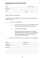
Page 23: ...battery instructions __________ Cirrus Plus wheelchair Warranty Battery Instructions only sealed lead acid or gel cell type batteries should be used Batteries must also be sealed deep cycle and maintenance free or battery will hinder vehicle performance and void the warranty _________ My dealer has instructed me on how to operate my Cirrus Plus wheelchair Signature ____________________________ Dea...

Page 24: ...Place Stamp Here 12 Harbor Park Drive Port Washington NY 11050 FOLD HERE FIRST FOLD HERE SECOND SEAL WITH TAPE DO NOT STAPLE ...

Page 25: ...12 Harbor Park Drive Port Washington NY 11050 Toll Free 877 224 0946 516 998 4600 Website www drivemedical com ...

Reviews: