background image

 49

1  특징

  �  �  �  �  �  �  �  �  �  �  �  �  �  �  �  �  �  �  �  �  �  �  �  �  �  �  �  �  �  �  �  �  �  �  �  �  �  �  �  �  �  �  �  �  �  �  �  �   50

2  포장

  �  �  �  �  �  �  �  �  �  �  �  �  �  �  �  �  �  �  �  �  �  �  �  �  �  �  �  �  �  �  �  �  �  �  �  �  �  �  �  �  �  �  �  �  �  �  �  �   50

  2.1  보관

�  �  �  �  �  �  �  �  �  �  �  �  �  �  �  �  �  �  �  �  �  �  �  �  �  �  �  �  �  �  �  �  �  �  �  �  �  �  �  �  �  �  �  �  �  �   50

  2.2 취급

  �  �  �  �  �  �  �  �  �  �  �  �  �  �  �  �  �  �  �  �  �  �  �  �  �  �  �  �  �  �  �  �  �  �  �  �  �  �  �  �  �  �  �  �  �  �   50

3 설치

�  �  �  �  �  �  �  �  �  �  �  �  �  �  �  �  �  �  �  �  �  �  �  �  �  �  �  �  �  �  �  �  �  �  �  �  �  �  �  �  �  �  �  �  �  �  �  �  �   50

  3.1 일반 

�  �  �  �  �  �  �  �  �  �  �  �  �  �  �  �  �  �  �  �  �  �  �  �  �  �  �  �  �  �  �  �  �  �  �  �  �  �  �  �  �  �  �  �  �  �   50

  3.2 필터링

  �  �  �  �  �  �  �  �  �  �  �  �  �  �  �  �  �  �  �  �  �  �  �  �  �  �  �  �  �  �  �  �  �  �  �  �  �  �  �  �  �  �  �  �  �   50

  3.3 윤활

  �  �  �  �  �  �  �  �  �  �  �  �  �  �  �  �  �  �  �  �  �  �  �  �  �  �  �  �  �  �  �  �  �  �  �  �  �  �  �  �  �  �  �  �  �  �   50


3.3.1 일반

  �  �  �  �  �  �  �  �  �  �  �  �  �  �  �  �  �  �  �  �  �  �  �  �  �  �  �  �  �  �  �  �  �  �  �  �  �  �  �  �  �  �  �   50


3.3.2 윤활유의 선택

  �  �  �  �  �  �  �  �  �  �  �  �  �  �  �  �  �  �  �  �  �  �  �  �  �  �  �  �  �  �  �  �  �  �  �  �  �  �   50


3.3.3 주입과 제거의 순서

  �  �  �  �  �  �  �  �  �  �  �  �  �  �  �  �  �  �  �  �  �  �  �  �  �  �  �  �  �  �  �  �  �  �  �   50

4 부속품

�  �  �  �  �  �  �  �  �  �  �  �  �  �  �  �  �  �  �  �  �  �  �  �  �  �  �  �  �  �  �  �  �  �  �  �  �  �  �  �  �  �  �  �  �  �  �  �   51

  4.1 전기적 부속품

  �  �  �  �  �  �  �  �  �  �  �  �  �  �  �  �  �  �  �  �  �  �  �  �  �  �  �  �  �  �  �  �  �  �  �  �  �  �  �  �  �   51


4.1.1 저주파 출력장치 (기본장착)

  �  �  �  �  �  �  �  �  �  �  �  �  �  �  �  �  �  �  �  �  �  �  �  �  �  �  �  �  �  �  �   51


4�1�2 Anti tampering�  �  �  �  �  �  �  �  �  �  �  �  �  �  �  �  �  �  �  �  �  �  �  �  �  �  �  �  �  �  �  �  �  �  �  �  �  �   51


4�1�3 Cyble sensor �  �  �  �  �  �  �  �  �  �  �  �  �  �  �  �  �  �  �  �  �  �  �  �  �  �  �  �  �  �  �  �  �  �  �  �  �  �  �   51


4.1.4 Medium & high frequency transmitters (옵션으로 제공)

  �  �  �  �  �  �  �  �  �  �  �  �  �  �  �  �  �   51

  4�2 Gasket-Filter  �  �  �  �  �  �  �  �  �  �  �  �  �  �  �  �  �  �  �  �  �  �  �  �  �  �  �  �  �  �  �  �  �  �  �  �  �  �  �  �  �  �   51

  4.3 외부 dryer cartridge

  �  �  �  �  �  �  �  �  �  �  �  �  �  �  �  �  �  �  �  �  �  �  �  �  �  �  �  �  �  �  �  �  �  �  �  �  �  �   51

5 시작 (Start-up)

�  �  �  �  �  �  �  �  �  �  �  �  �  �  �  �  �  �  �  �  �  �  �  �  �  �  �  �  �  �  �  �  �  �  �  �  �  �  �  �  �  �  �  �   51

  5.1 일반

  �  �  �  �  �  �  �  �  �  �  �  �  �  �  �  �  �  �  �  �  �  �  �  �  �  �  �  �  �  �  �  �  �  �  �  �  �  �  �  �  �  �  �  �  �  �   51

  5.2 By-pass와 함께 설치할 경우 

  �  �  �  �  �  �  �  �  �  �  �  �  �  �  �  �  �  �  �  �  �  �  �  �  �  �  �  �  �  �  �  �  �  �   51

  5.3 By-pass 없이 설치할 경우

�  �  �  �  �  �  �  �  �  �  �  �  �  �  �  �  �  �  �  �  �  �  �  �  �  �  �  �  �  �  �  �  �  �  �  �   51

  5.4 압력조정기 후단에 미터가 설치된 경우

�  �  �  �  �  �  �  �  �  �  �  �  �  �  �  �  �  �  �  �  �  �  �  �  �  �  �  �  �   52

  4�4 Flow limiters  �  �  �  �  �  �  �  �  �  �  �  �  �  �  �  �  �  �  �  �  �  �  �  �  �  �  �  �  �  �  �  �  �  �  �  �  �  �  �  �  �  �   52

6 유지보수

  6.1 미터의 유지보수

  �  �  �  �  �  �  �  �  �  �  �  �  �  �  �  �  �  �  �  �  �  �  �  �  �  �  �  �  �  �  �  �  �  �  �  �  �  �  �  �   52

  6.2 옵션장비의 유지 보수

�  �  �  �  �  �  �  �  �  �  �  �  �  �  �  �  �  �  �  �  �  �  �  �  �  �  �  �  �  �  �  �  �  �  �  �  �  �   52


6.2.1 저주파와 고주파 트렌스미터

�  �  �  �  �  �  �  �  �  �  �  �  �  �  �  �  �  �  �  �  �  �  �  �  �  �  �  �  �  �  �   52


6�2�2 Filter �  �  �  �  �  �  �  �  �  �  �  �  �  �  �  �  �  �  �  �  �  �  �  �  �  �  �  �  �  �  �  �  �  �  �  �  �  �  �  �  �  �  �   52

7 첨부

�  �  �  �  �  �  �  �  �  �  �  �  �  �  �  �  �  �  �  �  �  �  �  �  �  �  �  �  �  �  �  �  �  �  �  �  �  �  �  �  �  �  �  �  �  �  �  �  �   59

Summary of Contents for DELTA

Page 1: ...01 AJ 2019 07 02 Instruction manual Mode d emploi Betriebsanleitung Istruzioni d uso Manual de instrucciones Installatie voorschrift Kullanim Kilavuzu Manual de Instruções Manual de instrucţiuni Használati kézikönyv Gas Measurement ...

Page 2: ...14 30 EU EMC EN 60947 5 2 2007 A1 2012 EN 61000 6 2 2005 AC 2005 EN 61000 6 3 2007 A1 2011 AC 2012 3 Directive 2014 34 EU ATEX EN 60079 0 2012 A11 2013 EN 60079 11 2012 EN 13463 1 2009 EN 13463 5 2011 Certificate LCIE 06 ATEX 6031 X II 1 2 G Ex ia IIC T5 Ga Gb c T6 0081 LCIE 33 avenue General Leclerc F 92266 Fontenay aux Roses The module D is supervised by 0123 TÜV SÜD Product Service GmbH Ridlers...

Page 3: ...mitter furnished as standard 5 4 1 2 Anti tampering 5 4 1 3 Cyble sensor 5 4 1 4 Medium high frequency transmitters furnished as option 5 4 2 Gasket Filter 5 4 3 External dryer cartridge 5 4 4 Flow limiters 5 5 Start up 5 5 1 General 5 5 2 Installation with by pass 5 5 3 Installation without by pass 6 5 4 Meters placed after a regulator 6 6 Maintenance 6 6 1 Maintenance of the meter 6 6 2 Maintena...

Page 4: ...d in inch following ANSI ASME B1 1 1989 Metric threads and threads defined in inch are not compatible Please tighten bolts in opposite pairs A flexible coupling can be used to ensure a stress free in stallation The use of a filter placed upstream of the meter is advis able in gas with high particulate content See 3 2 Before installation The piping upstream of the meter should be free of dust Remov...

Page 5: ... 4 1 3 Cyble sensor ACyblesensorcanbeinstalledontothetotaliseratanytime seeAnnex4 TheCyblesensorisabounce freetransmitter It allows also the counting of eventual back flows 4 1 4 Medium high frequency transmitters furnished as option The meter can be delivered with medium or high frequency transmitters There are inductive sensors and connection is to a NAMUR type input circuit EN 60947 5 6 4 2 Gas...

Page 6: ... Maintenance 6 1 Maintenance of the meter Once installed the meter does not require any specific at tention except a periodical check or change of the lubricant filled in the covers After start up Natural gas After the preliminary term of service the lubri cant level should be checked Other gases After a working period of 100 hours from com missioning the lubricant level should be checked If the l...

Page 7: ...2007 A1 2012 EN 61000 6 2 2005 AC 2005 EN 61000 6 3 2007 A1 2011 AC 2012 3 2014 34 UE ATEX EN 60079 0 2012 A11 2013 EN 60079 11 2012 EN 13463 1 2009 EN 13463 5 2011 Avec certificat d approbation de type n LCIE 06 ATEX 6031 II 1 2 G Ex ia IIC T5 Ga Gb c T6 0081 LCIE 33 avenue General Leclerc F 92266 Fontenay aux Roses Le module D Annexe IV est supervisé par 0123 TÜV SÜD Product Service GmbH Ridlers...

Page 8: ...andard 10 4 1 2 Surveillance de ligne 10 4 1 3 Capteur Cyble 10 4 1 4 Emetteurs à moyenne haute fréquence disponible en option 10 4 2 Joint filtre 10 4 3 Cartouche silicagel externe 10 4 4 Limiteurs de débit 10 5 Mise en service 10 5 1 Généralités 10 5 2 Installation avec bi pass 11 5 3 Installation sans bi pass 11 5 4 Compteurs placés après un régulateur 11 6 Entretien 11 6 1 Entretien du compteu...

Page 9: ...tal lation où il pourrait être soumis à une accumulation d eau ou de particules L utilisation de bande téflon sur les raccords filetés doit êtrefaiteavecbeaucoupdeprécautiondemanièreàéviter d en introduire dans la chambre de mesure Lecompteurdoitêtreinstallésanscontraintessurlacanali sation Les brides doivent être alignées correctement Le compteur doit être considéré dans un système possi blement ...

Page 10: ... montage démontage ou réparation sur site du compteur uniquement des outils autorisés d emploi en zone explosive peuvent être utilisés Le compteur ne doit pas être exposé aux flammes radia tionsionisantes ultrasonsouàdeschampsélectromagné tiques puissants 4 1 1 Emetteur basse fréquence équipement standard Lecompteurestlivréavecundoubleémetteurd impulsions à basse fréquence L émetteur BF est consti...

Page 11: ...passer 0 3 bars par seconde S assurer de la dépressurisation complète du compteur Du gaz peut rester dans le compteur ou la canalisation c est pourquoi une ventilation suffisante est nécessaire 5 4 Compteurs placés après un régulateur L installation doit être effectuée conformément au manuel technique spécifique du régulateur Lors de la pressurisation ou de la dépressurisation il faut veiller à ce...

Page 12: ... 2 2007 A1 2012 EN 61000 6 2 2005 AC 2005 EN 61000 6 3 2007 A1 2011 AC 2012 3 Richtlinie 2014 34 EG ATEX EN 60079 0 2012 A11 2013 EN 60079 11 2012 EN 13463 1 2009 EN 13463 5 2011 mit EG Baumusterprüfungszertifikat Nr LCIE 06 ATEX 6031 X II 1 2 G Ex ia IIC T5 Ga Gb c T6 0081 LCIE 33 avenue General Leclerc F 92266 Fontenay aux Roses Das Modul D Anhang IV wird überwacht durch 0123 TÜV SÜD Product Ser...

Page 13: ...eber Standardausstattung 15 4 1 2 Anti Manipulationskontakt 15 4 1 3 Cyble Sensor 15 4 1 4 Mittel und Hochfrequenzimpulsgeber optional 15 4 2 Flachsieb 15 4 3 Externe Trockenpatrone für das Zählwerk 15 4 4 Durchflussbegrenzer 15 5 Inbetriebnahme 15 5 1 Allgemein 15 5 2 Installation mit Bypass 16 5 3 Installation ohne Bypass 16 5 4 Messgeräte nach einem Regler 16 6 Wartung 16 6 1 Wartung des Messge...

Page 14: ...n die Mess kammerhineinragt DasGerätmussspannungsfreiindieRohrleitungeingebaut werdenundalleFlanscheparallelausgerichtetsein Der Zähler muss in eventuellen Erdungsmaßnahmen be rücksichtigwerden Die Gewinde an UNC Flanschen sind nicht metrisch son dernnachANSI ASMEB1 1 1989 Metrische Gewinde sind nicht mit zölligen Gewinden kompatibel DieSchraubensindüberKreuzanzuziehen DurcheinflexiblesRohrstückka...

Page 15: ...dem Typenschild des MessgerätesundinAnlage4angegeben 4 1 2 Anti Manipulationskontakt Das Messgerät wird standardmäßig mit einem Anti Manipu lationskontakt geliefert Dabei handelt es sich um ein Schutz gaskontaktrelais welches normalerweise geschlossen ist Siehe Typenschild des Messgerätes bezüglich Polarität der Anschlüsse 4 1 3 Cyble Sensor Der Cyble Sensor kann jederzeit auf dem Zählwerk ange br...

Page 16: ... dem Abschalten immer noch Gas im Zähler befindet istunbedingtfüreineausreichendeBelüftungdes Installationsorteszusorgen 5 4 Messgeräte nach einem Regler Die Installation muss in Übereinstimmung mit dem techni schenHandbuchdesspezifischenReglerserfolgen Während dem Druckaufbau und der Druckentlastung ist sicherzustel len dass die Druckänderung 0 3 bar pro Sekunde nicht über schreitet 6 Wartung 6 1...

Page 17: ...C EN 60947 5 2 2007 A1 2012 EN 61000 6 2 2005 AC 2005 EN 61000 6 3 2007 A1 2011 AC 2012 3 2014 34 UE ATEX EN 60079 0 2012 A11 2013 EN 60079 11 2012 EN 13463 1 2009 EN 13463 5 2011 Con Certificato di Approvazione CE di Tipo n LCIE 06 ATEX 6031 X II 1 2 G Ex ia IIC T5 Ga Gb c T6 0081 LCIE 33 avenue General Leclerc F 92266 Fontenay aux Roses Il modulo D Annesso IV è supervisionato da 0123 TÜV SÜD Pro...

Page 18: ...dard 20 4 1 2 Dispositivo antifrode 20 4 1 3 Emettitore di impulsi Cyble 20 4 1 4 Emettitore di impulsi di media e alta frequenza fornito in opzione 20 4 2 Filtro a guarnizione 20 4 3 Essiccatore esterno 20 4 4 Limitatori di portata 20 5 Avviamento 20 5 1 Generalità 20 5 2 Installazione con by pass 21 5 3 Installazione senza by pass 21 5 4 Contatori posizionati dopo un regolatore 21 6 Manutenzione...

Page 19: ...nTeflonperserrareibul lonidifissaggiodelcontatore prestarelamassimaattenzio ne affinché nessun residuo di nastro venga introdotto nella cameradimisura Ilcontatoredovrebbeessereinstallatosenzacrearetensioni nella tubazione Le flange devono essere allineate corretta mente Ilcontatoreinstallato dovrebbeessereconnessonelsistema dimessaaterraesistente La filettatura della flangiatura UNC è espressa in ...

Page 20: ...ore in sito possono essere utilizzati solamente attrezzi idonei per utilizzoinareaconpericolodiesplosione Il contatore non dovrà essere esposto a fiamme radiazione ionizzataedultrasuonioforticampielettromagnetici 4 1 1 Emettitore d impulsi a bassa frequenza LF dotazione standard Il contatore viene solitamente fornito unitamente ad un dop piotrasmettitorediuscitaadimpulsiabassafrequenzaLF L e metti...

Page 21: ...0 3baralsecondo Delgaspuòessereancorarimastonelcontatoreeneltubo pertantoérichiestaunaventilazioneadeguata 5 4 Contatori posizionati dopo un regolatore L installazionedeveavvenireconformementealmanualetec nico dello specifico regolatore Durante la pressurizzazione e la depressurizzazione verificare che la variazione di pressione nonsiasuperiorea0 3baralsecondo 6 Manutenzione 6 1 Manutenzione del c...

Page 22: ...30 UE EMC EN 60947 5 2 2007 A1 2012 EN 61000 6 2 2005 AC 2005 EN 61000 6 3 2007 A1 2011 AC 2012 2 2014 34 UE ATEX EN 60079 0 2012 A11 2013 EN 60079 11 2012 EN 13463 1 2009 EN 13463 5 2011 Con el certificado de aprobación tipo CE n LCIE 06 ATEX 6031 X II 1 2 G Ex ia IIC T5 Ga Gb c T6 0081 LCIE 33 avenue General Leclerc F 92266 Fontenay aux Roses El módulo D Anexo IV es supervisado por 0123 TÜV SÜD ...

Page 23: ...ecuencia 25 4 1 2 Antifraude 25 4 1 3 Emisor cyble 25 4 1 4 Emisor de media y alta frecuencia se suministra como opción 25 4 2 Filtro de Malla 25 4 3 Cartucho del secador exterior 25 5 Puesta en servicio 25 5 1 General 25 5 2 Instalación con by pass 25 5 3 Instalación sin by pass 26 5 4 Contadores situados tras un regulador 26 4 4 Limitadores de flujo 26 6 Mantenimiento 26 6 1 Mantenimiento del co...

Page 24: ... UNC las roscas NO son métricas sino defini das en pulgadas siguiendo ANSI ASME B1 1 1989 Las roscas métricas y las roscas definidas en pulgadas no son compatibles Los tornillos deberán ajustarse con pares opuestos Para asegurar que la instalación no está sometida a esfuer zos puedeutilizarunacopleflexible conautorización ex presa de la empresa de distribución de gas En el caso de emplear gases co...

Page 25: ...suministranconemisorantifraude de estándar Se trata de un contacto por relé libre de poten cial encapsulado normalmente cerrado Véase la placa de características del contador para conocer los detalles de la conexión 4 1 3 Emisor Cyble El Emisor Cyble puede instalarse en cualquier momento so bre el totalizador ver anexo 4 El Emisor Cyble es un emisor depulsossinrebotes pudiendotenerencuentaloscauda...

Page 26: ...ador específico Durante la presuriza ción y la despresurización asegúrese de que la variación de la presión no exceda los 0 3 bar por segundo 6 Mantenimiento 6 1 Mantenimiento del contador Unavezinstalado elcontadornorequiereningunaatención específica excepto una comprobación periódica o cambio del lubricante contenido en los carters Después de la puesta en servicio Gas natural tras finalizar la d...

Page 27: ...60947 5 2 2007 A1 2012 EN 61000 6 2 2005 AC 2005 EN 61000 6 3 2007 A1 2011 AC 2012 3 2014 34 EU ATEX EN 60079 0 2012 A11 2013 EN 60079 11 2012 EN 13463 1 2009 EN 13463 5 2011 Met CE modelgoedkeuring certificaat nr LCIE 06 ATEX 6031 X II 1 2 G Ex ia IIC T5 Ga Gb c T6 0081 LCIE 33 avenue General Leclerc F 92266 Fontenay aux Roses De module D Bijlage IV staat onder supervisie van 0123 TÜV SÜD Product...

Page 28: ...r standaard geleverd 30 4 1 2 Antifraude schakeling 30 4 1 3 Cyble sensor 30 4 1 4 Midden frequent Hoog frequent impulsgever optioneel 30 4 2 Filter 31 4 3 Extern droogelement 31 4 4 Stroombegrenzers 31 5 Opstarten 31 5 1 Algemeen 31 5 2 Installatie met bypass 31 5 3 Installatie zonder bypass 31 5 4 Gasmeters geplaatst achter een regelaar 31 6 Onderhoud 32 6 1 Onderhoud van de meter 32 6 2 Onderho...

Page 29: ...er terecht kan komen De meter moet spanningsvrij in het leidingsysteem wor den geïnstalleerd Flenzen moeten correct worden uitge lijnd Demetermoetbeschouwdwordenalsonderdeelvaneen mogelijk aardingssysteem Bij UNC flensaansluiting is de schroefdraad in inch volgens ANSI ASME B1 1 1989 en is dit GEEN metrische draad MetrischeschroefdraadenInchschroefdraadzijnniet compatibel De bouten dienen kruislin...

Page 30: ...rden gebruikt om de olie af te tappen Afhankelijk van de positie van de meter dient het peilglas L1 of L2 te worden gebruikt om de juiste hoe veelheid olie tijdens het vullen te kunnen waarnemen De olie moet via plug F worden toegevoegd totdat het via opening L uitstroomt Enkelhetlaagstgeplaatstepeilglas dient te worden gebruikt om het juiste oliepeil te kunnen controleren Inallegevallengeldt vull...

Page 31: ... zetten Openalsdeuitlaatdrukinevenwichtis langzaamdekleine afsluiteraandeinlaatzijdeV1 Dedrukveranderingmag0 3 bar per seconde niet overschrijden Openalsdedrukindegasmeterinevenwichtislangzaam de afsluiter aan de inlaatzijde en sluit vervolgens V1 Open langzaam de afsluiter aan de uitlaatzijde en contro leerofdegasmeterdedoorgelatengasstroomregistreert Sluitgeleidelijkenopeenlangzamewijzedebypass ...

Page 32: ...orden ververst Overige gassen Raadpleeg ITRON a u b Gebruik voor reiniging van de meter een vet en alcohol vrij product Reparatie mag alleen worden uitgevoerd door deskundig personeel Na iedere reparatie dient een dichtheid test van 1 1 x PS Pmax worden uitgevoerd Indien een zgn nat gas wordt gemeten dient controle op inwendige en uitwendige corrosie regelmatig te worden uitgevoerd Inextremegevall...

Page 33: ...2007 A1 2012 EN 61000 6 2 2005 AC 2005 EN 61000 6 3 2007 A1 2011 AC 2012 3 2014 34 AT ATEX EN 60079 0 2012 A11 2013 EN 60079 11 2012 EN 13463 1 2009 EN 13463 5 2011 AT tip onay sertifika numarası LCIE 06 ATEX 6031 X II 1 2 G Ex ia IIC T5 Ga Gb c T6 0081 LCIE 33 avenue General Leclerc F 92266 Fontenay aux Roses Modül D Ek IV 0123 TÜV SÜD Product Service GmbH Ridlerstr 65 D 80339 München tarafından ...

Page 34: ...andart olarak sağlanmaktadır 36 4 1 2 Müdahaleye karşı 36 4 1 3 Cyble sensörü 36 4 1 4 Orta yüksek frekanslı vericiler opsiyon olarak sağlanmaktadır 36 4 2 Sızdırmazlık Contası Filtre 36 4 3 Dışkurutucu kartuş 36 4 4 Debi limitleyicisi 36 5 Devreye alma 36 5 1 Genellikler 36 5 2 Baypas ile tesisat döşeme 37 5 3 Baypas sız kurulum 37 5 4 Regülatörden sonra yerleştirilen sayaçlar 37 6 Bakım 37 6 1 S...

Page 35: ...zdırmazlığını sağlamak için teflon bant kullanılırsa o zaman ölçüm odacığına bantın girmesini engellemek için çok dikkat edilmesi ge rekmektedir Sayaç boru sistemine zorlama olmadan monte edil mesi gerekiyor Flanşlar doğru olarak sıralanması gerekiyor UNC flanşlarda dişler metrik DEĞİLDİR ama inch ile tanımlanır takip eden ANSI ASME B1 1 1989 Metrik dişler ve inch ile tanımlanan dişler uyumlu deği...

Page 36: ...n olmalıdır unutmayın ki sayacın değiştirilmesi sırasındaki tehlikeli bölge sınıflandı rılması normal sayaç çalışma sırasındakinden farklı olabilir Sayaç aleve iyonlaşmış radyasyona ultrason veya güçlü bir elektromanyetik alana maruz kalmama lıdır 4 1 1 Düşük Frekans vericisi standart olarak sağlanmaktadır Sayaç genellikle çift LF pulse çıkış vericisi ile teslim edilmektedir LF kuru bir reed switc...

Page 37: ...z V2 vanasının küçük çeşmesini yavaşça açınız Ba sınç değişikliği saniyede 0 3 bar ı geçmemelidir Bazı gazlar sayacın ve borunun içerisinde kalabi liyor o nedenle yeterli havalandırma gerekmek tedir 5 4 Regülatörden sonra yerleştirilen sayaçlar Tesisat döşeme belirli regülatörün teknik kılavuzuna uygun olarak yapılmalıdır Basınçta tutma veya basınç tan alma esnasında basınç değişikliğinin saniyede...

Page 38: ... EN 60947 5 2 2007 A1 2012 EN 61000 6 2 2005 AC 2005 EN 61000 6 3 2007 A1 2011 AC 2012 3 2014 34 UE ATEX EN 60079 0 2012 A11 2013 EN 60079 11 2012 EN 13463 1 2009 EN 13463 5 2011 Com certificado de aprovação tipo EC n LCIE 06 ATEX 6031 X II 1 2 G Ex ia IIC T5 Ga Gb c T6 0081 LCIE 33 avenue General Leclerc F 92266 Fontenay aux Roses O módulo D Anexo IV é supervisionado por 0123 TÜV SÜD Product Serv...

Page 39: ...a fornecido como padrão 41 4 1 2 Anti fraude 41 4 1 3 Sensor Cyble 41 4 1 4 Transmissores de alta e média freqüência fornecidos como opção 41 4 2 Filtro tipo junta Gasket 41 4 3 Cartucho externo de silicagel 41 4 4 Limitadores de fluxo 41 5 Partida 41 5 1 Geral 42 5 2 Instalação com by pass 42 5 3 Instalação sem by pass 42 5 4 Medidores instalados após regulador 42 6 Manutenção42 6 1 Manutenção do...

Page 40: ...ges devem estar corretamente alinhados O medidor deve ser considerado em um possível sistema aterrado Em flanges padrão UNC as roscas não são métricas mas definidasemPolegadas conformeANSI ASMEb1 1 1989 Roscasmétricase roscasdefinidasempolegadasnão são compatíveis Por favor o aperto dos parafusos deve ser feito em pares opostos em cruz Um acoplamento flexível pode ser usado para assegurar uma inst...

Page 41: ...açãodeárea de risco durante a troca do medidor pode ser diferente de quando o medidor estiver em condições normais de operação Omedidornãodeveserexpostoaofogo radiaçãoionizan te ultra som ou forte campo eletromagnético 4 1 1 Transmissores de baixa freqüência fornecidos como padrão Omedidorénormalmentefornecidocomduplotransmissor de pulso de baixa freqüência LF O LF é um contato seco e normalmente ...

Page 42: ...da tubula ção por isso é necessária ventilação suficiente 5 4 Medidores instalados após um regulador Ainstalaçãodeveráserfeitadeacordocomomanualtécnico do regulador específico Durante a pressurização e despres surização assegure sequeavariaçãodepressãonãoexceda 0 3 bar por segundo 6 Manutenção 6 1 Manutenção do medidor Umavezinstalado omedidornãorequernenhumaatenção específica exceto uma checagem ...

Page 43: ...7 A1 2012 EN 61000 6 2 2005 AC 2005 EN 61000 6 3 2007 A1 2011 AC 2012 3 2014 34 EU ATEX EN 60079 0 2012 A11 2013 EN 60079 11 2012 EN 13463 1 2009 EN 13463 5 2011 Cu certificatul de aprobare CE numărul LCIE 06 ATEX 6031 X II 1 2 G Ex ia IIC T5 Ga Gb c T6 0081 LCIE 33 avenue General Leclerc F 92266 Fontenay aux Roses Modulul D Anexa IV este supervizat de 0123 TÜV SÜD Product Service GmbH Ridlerstr 6...

Page 44: ... ca standard 46 4 1 2 Antifraudă 46 4 1 3 Cyble senzor 46 4 1 4 Transmiţătoare de medie şi joasă frecvenţă furnizate optional 46 4 2 Garnitură Filtru 46 4 3 Cartuş uscare extern 46 4 4 Limitatoarele de debit 46 5 Punerea în funcţiune 46 5 1 Generalități 46 5 2 Instalarea cu by pass 47 5 3 Instalarea fără by pass 47 5 4 Contoare amplasate după regulator 47 6 Întreținere 47 6 1 Întreținerea contorul...

Page 45: ...e utilizată pentru etanşarea îmbinărilor cu filet atunci trebuie avută cea mai mare atenție pentru a evita introducerea de bandă în camera de măsurare Contorul trebuie să fie instalat fără stres în conducte Flanșele trebuie să fie corect aliniate Contorul trebuie să fie luat în considerare într un posibil sistem cu împământare LaflanşecufiletUNC filetulnuestemetric dardefinitîn inch respectând ANS...

Page 46: ...îndepărtarea sau repararea contorului pe site trebuie să fie adecvate zonelor periculoase având în vedere că aceste zone pot diferi în funcție de amplasarea contorului Contorul nu trebuie expus la flamă ionizare radiații ultrasunete sau câmp puternic electromagnetic 4 1 1 Transmițătoarele de joasă frecvență furnizate standard În mod normal contorul este livrat cu două transmițătoare LF Transmițăto...

Page 47: ...ă regulator Instalarea trebuie să se facă în concordanţă cu manu alul tehnic al regulatorului În timpul presurizării și a depresurizării asigurați vă că variația de presiune nu depășește 0 3 bar secundă 6 Întreţinere 6 1 Întreţinerea contorului Odată instalat contorul nu necesită o întreținere specială cu excepția verificării periodice a uleiului După pornire Gaz natural După termenul preliminar d...

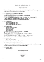
Page 48: ...000 6 3 2007 A1 2011 AC 2012 3 2014 34 EU ATEX EN 60079 0 2012 A11 2013 EN 60079 11 2012 EN 13463 1 2009 EN 13463 5 2011 EC 형식 승인 인증서 n LCIE 06 ATEX 6031 X II 1 2 G Ex ia IIC T5 Ga Gb c T6 0081 LCIE 33 avenue General Leclerc F 92266 Fontenay aux Roses Module D Annex IV 는 아래의 기관에 의해 감독됩니다 0123 TÜV SÜD Product Service GmbH Ridlerstr 65 D 80339 München EC 형식 승인 인증서 n EX2A 17 05 70229 004 4 2014 32 EU...

Page 49: ...본장착 51 4 1 2 Anti tampering 51 4 1 3 Cyble sensor 51 4 1 4 Medium high frequency transmitters 옵션으로 제공 51 4 2 Gasket Filter 51 4 3 외부 dryer cartridge 51 5 시작 Start up 51 5 1 일반 51 5 2 By pass와 함께 설치할 경우 51 5 3 By pass 없이 설치할 경우 51 5 4 압력조정기 후단에 미터가 설치된 경우 52 4 4 Flow limiters 52 6 유지보수 6 1 미터의 유지보수 52 6 2 옵션장비의 유지 보수 52 6 2 1 저주파와 고주파 트렌스미터 52 6 2 2 Filter 52 7 첨부 59 ...

Page 50: ...고려해야 설치 해 야 한다 UNC 나사산 플랜지에서 나사산은 미터가 아니라 ANSI ASME B1 1 1989에 정의된 인치에 따릅니다 미터 나사산과 인치 나사산은 호환되지 않습니다 볼트를 조일때는 반대편 볼트를 짝으로 하여 조이 세요 뒤틀림 없는 설치를 위해 플렉서블 커플링을 사용 할 수 도 있습니다 이물질이 많은 가스에 사용될 경우 전단에 필터를 사용하는 것을 추천합니다 3 2항을 참고하세요 설치전 미터의 전단 배관에는 이물질이 없어야 합니다 보호 캡을 제거 하세요 미터 몸체에 있는 화살표와 가스가 흐르는 방향이 맞는지 확인하세요 임펠러가 잘 움직이는지 확인하세요 계량기에 조 립되는 가능한 액세서리들은 녹방지처리를 간섭하 지 말아야 한다 계량기에 조립되는 가능한 액세서리들은 녹방지처 리를 간섭하지 말아야...

Page 51: ...지스터에 언제나 설치될 수 있 습니다 첨부 4을 참고하세요 사이블 센서는 바운스 가 생기지 않는 트렌스미터이며 역류를 카운트하기 도 합니다 4 1 4 Medium high frequency transmitters 옵션으로 제공됩니다 미터에는 중주파 혹은 고주파 트렌스미터가 설치 될 수 있습니다 Inductive sensor이며 연결은 NAMUR type input circuit EN 60947 5 6 을 이용합니다 4 2 Gasket Filter 가스켓필터는 미터 전단 기본 가스켓의 위치에 삽입 될 수 있습니다 전단 배관에 남아있을 수 있는 이물 질을 걸러내기 위한 것입니다 공급개시 4 8주에 제 거 해주는 것을 추천합니다 4 3 외부 dryer cartridge 미터는 설치환경이 좋지 않을 경우 외부 실리...

Page 52: ...up 후 천연가스 서비스 조건에 따라 윤활유 레벨을 반드시 확인해야 합니다 기타 가스 시운전후 100시간의 작동 후 윤활유 레벨 을 반드시 확인해야 합니다 만일 윤활유 레벨이 눈에 띄게 낮거나 윤활유가 유 화되었거나 윤활유와 가스간에 화학적 반응이 있다 면 윤활유는 재검토되고 알맞은 조건의 것으로 교체 되어야 합니다 윤활유의 교체시기 윤활유의 점검 및 교체주기는 운영 조건에 달려 있습 니다 압력변화 유량 천연가스 일반적인 환경하에 윤활유는 5 8년 마다 교체하여야 한다 만일 미터가 매우 깨끗한 가스에서 사용된다면 기간은 연장될 수 있습니다 기타 가스 저희에게 문의해 주세요 미터의 청소하기 위해서는 솔벤트와 알코올이 없는 제품을 사용해 주세요 수리는 자격이 있는 사람에 의해 이루어져야 하며 최대압력의 1 1배...

Page 53: ... EN 60947 5 2 2007 A1 2012 EN 61000 6 2 2005 AC 2005 EN 61000 6 3 2007 A1 2011 AC 2012 3 2014 34 EU ATEX EN 60079 0 2012 A11 2013 EN 60079 11 2012 EN 13463 1 2009 EN 13463 5 2011 EK típusvizsgálati tanúsítvány LCIE 06 ATEX 6031 X II 1 2 G Ex ia IIC T5 Ga Gb c T6 0081 LCIE 33 avenue General Leclerc F 92266 Fontenay aux Roses D modult felügyeli 0123 TÜV SÜD Product Service GmbH Ridlerstr 65 D 80339 ...

Page 54: ...ndard felszereltség 56 4 1 2 Manipuláció gátló 56 4 1 3 Cyble szenzor 56 4 1 4 Közép és magas frekvenciás jeladó opcionális felszereltség 56 4 2 Lapszűrő 56 4 3 Külső szárítópatron 56 4 4 Áramlás Határoló 57 5 Indítás 57 5 1 Általános 57 5 2 Telepítés áthidalóval 57 5 3 Telepítés áthidaló nélkül 57 5 4 A szabályozó után elhelyezett mérőórák 57 6 Karbantartás 57 6 1 A mérőóra karbantartása 57 6 2 A...

Page 55: ...sznál a menetes csatlakozások rá szorításához akkor különös figyelmet kell fordítani arra hogy elkerülje a szalag bejutását a mérőkamrába A gázmérőórát a csőrendszerre kifejtett erőteljes hatás nélkül szerelje fel A peremeknek pontosan kell illesz kedniük A mérőt védőföldeléssel ellátott rendszerben szabad telepíteni UNC csavarmenetes peremeken a menetek NEM metrikusan hanem hüvelykben kerülnek me...

Page 56: ...erint Csak a mérőóra fejét tisztítsák meg átitatott törlőken dővel A szabadon álló alumínium alkatrészeket megfelelően kell védeni festék lakk stb használatával amennyiben a környezetben rozsdarétegek képződhetnek a porból A mérőóra teljes telepítését villámcsapás veszélye te kintetében is át kell gondolni A mérőórahelyszínitelepítéséhez eltávolításáhozvagy javításához használt szerszámoknak meg k...

Page 57: ...térés nem haladhatja meg a másodpercenkénti 0 3 bar ér téket Ha a nyomás kiegyenlítődött nyissa ki teljesen a felső szakasz szelepét Lassan nyissa ki az alsó szakasz szelepét A szelepet kis mértékben kell kinyitni az alábbiak fenntartásához A felső szakasz nyomása a mérőóra vonalában Az áramlási sebesség a mérőórában az alsó szakasz nyomás alá helyezése során kb 5 Qmax Ha az alsó szakasz nyomása k...

Page 58: ...yomástartó alkatrészeket cserélnek győződjenek meg arról hogy a tartozékok megfelelnek a PED előírá sainak 6 2 Az opcionális felszerelések karbantartása 6 2 1 LF és HF jeladók Ezen jeladók nem igényelnek különleges karbantartást A jeladók működése az elektronikai index és a mérőóra index összehasonlításával ellenőrizhető 6 2 2 Szűrők Ha a nyomásveszteség növekedését észlelik a szűrőt el lenőrizni ...

Page 59: ...ones recomendadas Installatie voorschrift Tavsiye edilen döşeme Instalação Recomendada D L Flange meters with holes threaded Faceoftheflange No installation at low point in the network Installation free of tensions Impellers must be horizontal processioned Visual inspection at the reception Not welding the installed meter ...

Page 60: ...20 6 24 24 28 100 50 300 8 5 8 UNC 2B 127 28 100 50 600 8 5 8 UNC 2B 127 28 100 80 150 125 4 5 8 UNC 2B 152 4 24 24 100 100 150 125 8 5 8 UNC 2B 190 5 24 24 100 Flanged meters with holes NOT threaded Meters DN150 G250 to G650 S3 Flow are available with flanged connections Holes in the flanges are not threaded PN 10 16 Class 150 DN Number of holes ø f Diameter D mm T 150 8 22 4 241 26 Notes Install...

Page 61: ...N50 S1 Flow Oil level is cor rect when oil flows out of the level point L Verticalgasflow Horizontalgasflow L F F F L D D F F F Aluminium DN80 DN100 Ductile Iron DN80 DN100 DN150 Correct oil level Verticalgasflow Horizontalgasflow F F F D L F F F D L Compact DN25 DN40 DN50 Verticalgasflow Correct oil level Horizontalgasflow F F F L D D L SE DN50 DN80 Evo DN50 DN80 DN100 Verticalgasflow Correct oil...

Page 62: ...ntrinsically safe circuits EN 60079 0 11 For ATEX products intrinsically safe circuits EN 60079 0 11 Power rating Max 10 W Max 120 mW Max 64 mW Voltage Break down Max 180 V dc Max 15 V dc Max 15 V dc Current Switching Max 50 mA Max 50 mA Max 50 mA Capacitance and Inductance C 0F L 0H C 0F L 0H C 90ƞF L 250 µH Operation temperature range 30 C to 60 C 30 C to 60 C 30 C to 60 C Following recommend va...

Page 63: ...sansbipasse InstallationohneBypass Installazionesenzaby pass Instalación sin by pass Installatie zonder by pass Baypas sız kurulum Instalação sem by pass Annex 7 Pete s plug option Option Pete s plug Pete s Steckeroption Opzione Pete s Plug Pete s plug optie Pete s plug opsiyonu Opção do Pete s Plug Cross section 1 Cap and gasket 2 Cap retaining strag 3 Two self closing valves with interaction to ...

Page 64: ...h America LLC All rights reserved Dresser Utility Solutions reserves the right to make changes in specifications and features shown herein or discontinue the product described at any time without notice or obligation Contact your Dresser Utility Solutions representative for the most current information The Dresser Logo and all Trademarks containing the term Dresser are the property of Dresser LLC ...

Reviews: