Dreaming Robots Camera Axe 5 User Manual Download Page 8

Yes

when the Activate button is pressed, to put the unit 
into photo mode, causing the camera to pre-focus 
(if the camera supports this capability).
NOTE: Leave this set to No for flashes.
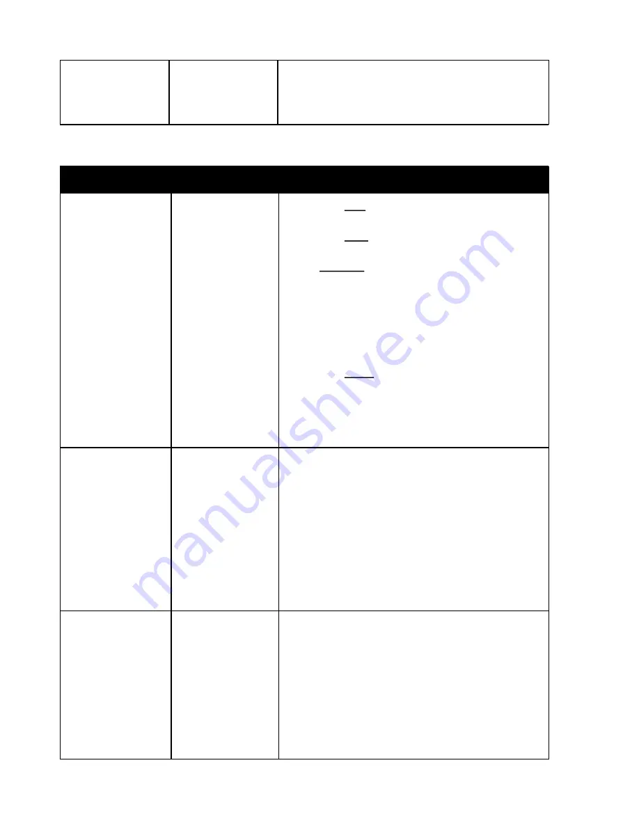
Device Settings


Prameter

Options

Description

Trigger Type

Low
High
Threshld
Digital

A setting of Low will trigger when the sensor 
reading is lower than the setting.
A setting of High will trigger when the sensor 
reading is higher than the setting
With a Threshld setting, when you activate the 
sensor it records the base value and then a trigger 
happens when a difference greater than the 
threshold value is recorded.  Then once the bulb 
has finished, a new base value is recorded.  See 
the example in the Light Sensor section of the 
document for how this would be used.
A setting of Digital will cause digital readings to be 
taken instead of analog readings.  So instead of a 
reading from 0 to 999 you will only get a 0 (low) or 
1 (high).  This mode is faster, but will not work with 
sensors that depend on analog readings.

Trigger Value

Numeric value 
between 000 and 
999
 
Or Hi/Low if 
Trigger Type set to 
Digital

First value is the trigger value you set, and second 
value is the current value read by sensor.  The 
current sensor value, which is displayed to the left 
of this value, is updated every 500 ms.
When set to a trigger type of Threshld, the 
updating value is the difference between the high 
and low sensor readings during that sampling 
period.
If trigger type is set to digial then this will dislay Hi 
or Low instead of a number.

Power

On
Off_Dev1
Off_Dev2

This setting allows the sensor to be turned off 
when the device associated with that sensor is 
triggered.  
For example, if there is a laser sensor connected 
to the Sensor1 port and a light sensor connected 
to the Sensor2 port.  You could set Device1 
(camera) to trigger based on input from sensor2 
(light sensor).  Then if Sensor1 (laser) turns it’s 
power off based on to Device2 (camera linked to 

Summary of Contents for Camera Axe 5

Page 1: ...Camera Axe 5 User Manual Document Version 5 2a December 18 2011 Authors Andrew Morgan and Maurice Ribble ...

Page 2: ...tons Camera Flash Buttons Camera Flash LEDs Camera Flash Ports Sensor Ports USB Port Menus Advanced Sensor Menu Projectile Menu Valve Menu Intervalometer Menu General Settings Menu Sensors Light Sensor Laser Sensor Microphone Sensor Projectile Sensor Valve Sensor Photogate Sensor Motion Distance Sensor Camera Shutter Sync Sensor Clip Sensor Multi Flash Board ...

Page 3: ...r The user must supply an Arduino Uno or compatible development board and a way to power the device Since this version gets it s power from the Arduino there is no power switch This version does not come with an enclosure This shield version does use the same software and has all the same functionality as the standard Camera Axe 5 in a much cheaper package for the DIY Maker crowd Hardware The top ...

Page 4: ...he Activate button is depressed during the startup process the unit will be reset to the factory default values Select Button The select button toggles the edit mode on and off When in edit mode the value of individual parameters can be adjusted using the arrow buttons When not in edit mode the arrow buttons move from field to field within the current menu Only one value can be selected changed at...

Page 5: ...Camera Axe are camera flash ports These ports are labeled Camera Flash 1 and Camera Flash 2 These ports are used to connect either a camera or flash to be triggered The Camera Flash 1 port is named Device 1 in the menus and the Camera Flash 2 port is named Device 2 The way the Camera Axe triggers cameras and flashes is by allowing current to pass through and the camera or flash provides the voltag...

Page 6: ...the middle sensor pin works analogRead This returns an analog value between 0 and 1023 proportional to the sensor voltage of 0 to 5 volts The Camera Axe displays values from 0 to 999 This is the slower way to read the sensor value still quite fast at 20 microseconds but it provides the ability to read the range of values from the sensor This method is used by the Advanced Sensor menu to allow trig...

Page 7: ...ngs available for each parameter and a brief description of the function of that parameter Parameter Options Description Trigger Sensor Sensor1 Sensor2 S1_or_S2 S1_and_2 None This setting determines which sensor triggers the device For example if Device1 is set with Trigger Sensor Sensor1 then when sensor 1 is triggered device 1 will fire When S1_or_S2 is selected the device will fire if either se...

Page 8: ...ing from 0 to 999 you will only get a 0 low or 1 high This mode is faster but will not work with sensors that depend on analog readings Trigger Value Numeric value between 000 and 999 Or Hi Low if Trigger Type set to Digital First value is the trigger value you set and second value is the current value read by sensor The current sensor value which is displayed to the left of this value is updated ...

Page 9: ...ter Options Description Distance Numeric value between 00 0 and 99 9 The distance from the second sensor LED to the position of the projectile when the flash fires Low High Trigger Low High Determines whether to trigger on low or high sensor values The projectile sensor has high values when nothing is between the sensors so this should be set to a value of Low when using the projectile sensor desc...

Page 10: ... the valve will be open to release a drop V1 Drop2 Delay Numeric value between 000 and 999 The number of milliseconds after the first drop to start the second drop V1 Drop2 Size Numeric value between 000 and 999 The number of milliseconds that the valve will be open to release the second drop Flash Delay Numeric value between 000 and 999 The number of milliseconds to wait after the second drop to ...

Page 11: ...2 Delay Numeric value between 000 and 999 The number of milliseconds after the first drop to start the second drop V2 Drop2 Size Numeric value between 000 and 999 The number of milliseconds that the valve will be open to release the second drop To use this menu plug the valve sensor into Sensor 1 and make sure it is turned on Plug an external flash into Camera Flash 1 and plug the camera into Came...

Page 12: ...e HDR is accomplished by doubling the bulb time for each shot see the example below For this mode to work your camera must be in bulb mode Mirror Lockup Yes No This adds another shutter trigger for each shot To use this your camera must support mirror lockup and have that setting enabled The camera is triggered to raise the mirror and then two seconds later to allow the vibration to settle there i...

Page 13: ...the unit is set to turn off the backlight after 10 seconds pressing the Activate button to enter photo mode will also turn off the backlight The backlight is the largest contributing factor to power usage on the Camera Axe so turning it off greatly extends battery life This menu lets you control the startup mode and switch between preset groups as described below The menu also shows the current ve...

Page 14: ... c digitalWrite SENSOR1_PIN HIGH digitalWrite SENSOR2_PIN HIGH However this change is not recommended because the pull up resistors can affect some of the sensors readings It was better to just not be able trust the values if no sensor is connected than have the pull up resistors affect the readings Schematics part lists and circuit board layouts are available for each of the sensors described bel...

Page 15: ...hed a new base value is recorded This works well for sunsets where you want to take a picture as the light changed gradually Laser Sensor The laser sensor isn t really a sensor in that it doesn t trigger a device but it can be used with the light sensor to create a beam of light that can be broken to trigger the light sensor When using the Advanced Sensor menu as described above when the laser is ...

Page 16: ...when the light sensor value goes below 100 this value may need to be adjusted up or down depending on the sensor reading when the laser is on verses off the light sensor Microphone Sensor The microphone sensor is a basic sound activated sensor that is used to trigger devices based on sharp loud sound changes An example of how the microphone sensor would be used is described below Using a microphon...

Page 17: ...nnected to the Camera Flash 1 and or the Camera Flash 2 ports When the unit is in photo mode the code loops watching for the first sensor to be triggered then waits for the second sensor to be triggered The time between the two sensor events is used to determine the speed of the projectile This speed is then used to determine the time delay before triggering the flash When the delay time is reache...

Page 18: ...tions The first is to trigger it manually with a fairly long exposure like 5 seconds just before you activate the valve sensor The second option and I think this is a little easier is to connect your camera to the Camera Axe s Camera Flash 1 port and put your camera s exposure to bulb so the Camera Axe can trigger your camera You will need to connect one or more flashes to the Camera Flash 2 port ...

Page 19: ...rger and it is accurate enough to detect a movement of just a few inches Camera Shutter Sync Sensor This Camera Shutter Sync sensor which plugs into either of the sensor ports on the Camera Axe detects when the shutter of your camera is open To use this your camera must have a pc sync port By default most cameras will trigger this when the shutter has just opened front curtain sync but most camera...

Page 20: ...etween the two clips a manual button two sheets of tinfoil the touch each other when someone steps on it a thin metal trip wire a photo resistor or many other things Multi Flash Board This board plugs into the one of the Camera Axe s Camera Flash ports and replicates that signal to up to 4 more devices Normally that would be 4 flashes but it could be 4 cameras Each device is isolated from the othe...

Reviews: