


15
5.
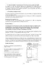
Proposal for size and connection of the storage tank to a heating system
An ideal size of the accumulation tank is designed by a design engineer, or a person sufficiently qualified
to design heating systems.
Product assembly must be implemented by an authorised person (confirmed in the warranty certificate).
Prior to commissioning, we recommend that you run the heating circuit and any impurities that are
trapped in the filter clean, then the system is fully operational.
6.
General Technical Parameters
The maximum operating pressure in the tank is 0.3 MPa. The maximum heating water temperature in the
tank is 90°C.
The maximum operating pressure in the inner tank is 0.6 MPa. The maximum hot service water
temperature in the inner tank is 90°C.
In version 2 a 3 additionally:
The maximum operating pressure in the exchanger is 1 MPa, the maximum temperature of heating water
in the exchanger is 110°C.
Important: When putting into operation, water has to be filled first into the inner tank for HSW
and the operating pressure inside it has to be kept, only then heating water can be filled into the
outer accumulation tank, otherwise the product may get damaged!
The manufacturer explicitly emphasises the necessity of being particular in testing the tightness of
the heating circuit (radiators, piping joints, floor heating, etc.) with the connection of the
accumulation tank. No pressure grow in the accumulation tank heating water compartment may
occur above the maximum operating pressure of 0.3 MPa, if the heating system is pressurised to
higher than the maximum operating pressure, the inner enamelled tank may get permanently
damaged!
No stop fitting can be put between the security fitting of the heating circuit and the accumulation
tank!!!
It is recommended to use the product in an indoor environment with air temperatures from +5°C to 45°C
and a maximum relative humidity of 80%.
Safety valve has to be fitted on the cold water inlet. Each hot service water pressure heater must have a
safety valve with a membrane spring. Nominal clearance of safety valves is defined in the ČSN 0 60830
standard. The heaters are not equipped with a safety valve. The safety valve must be easily accessible, as
close to the heater as possible. The input pipes must have at least the same clearance as the safety valve.
The safety valve is placed high enough to secure dripping water drain by gravity. We recommend
mounting the safety valve onto a branch pipe. This allows easier exchange without having to drain the
water from the heater. Safety valves with fixed pressure settings from the manufacturer are used for the
assembly. Starting pressure of a safety valve must be identical to the maximum allowed heater pressure,
and at least 20% higher than the maximum pressure in the water main. If the water main pressure exceeds
such value, a reduction valve must be added to the system.
No stop valves can be put between the heater
and the safety valve. During the assembly, follow the guide provided by the safety equipment
manufacturer. It is necessary to check the safety valve each time before putting it into operation. It is
checked by manual moving of the membrane from the seat, turning the make-and-break device button
always in the direction of the arrow. After being turned, the button must click back into a notch. Proper
function of the make-and-break device results in water draining through the safety valve outlet pipe. In
common operation, such a check needs to be implemented at least once a month, and after each heater
shutdown for more than 5 days. Water may be dripping off the drain pipe of the safety valve; the pipe
must be open into the air, pointed down; environment temperatures must not drop below zero.
When draining the heater, use a recommended drain valve. First, close water input into the heater.
Summary of Contents for NADO
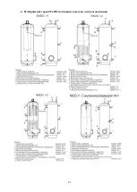
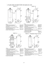
Page 4: ...4 4 Zobrazení verzí NADO a popis vývodů ...
Page 11: ...11 4 Abbildung der Versionen NADO und Beschreibung der Auslässe ...
Page 14: ...14 4 Illustration on NADO versions and description of outlets ...
Page 18: ...18 4 Az egyes NADO verziók ábrái és a kivezetések ismertetése ...
Page 21: ...21 4 Изображение серии NADO и описание выходов для подсоединения ...
Page 25: ...25 4 Représentation du modèle NADO et description des sorties ...