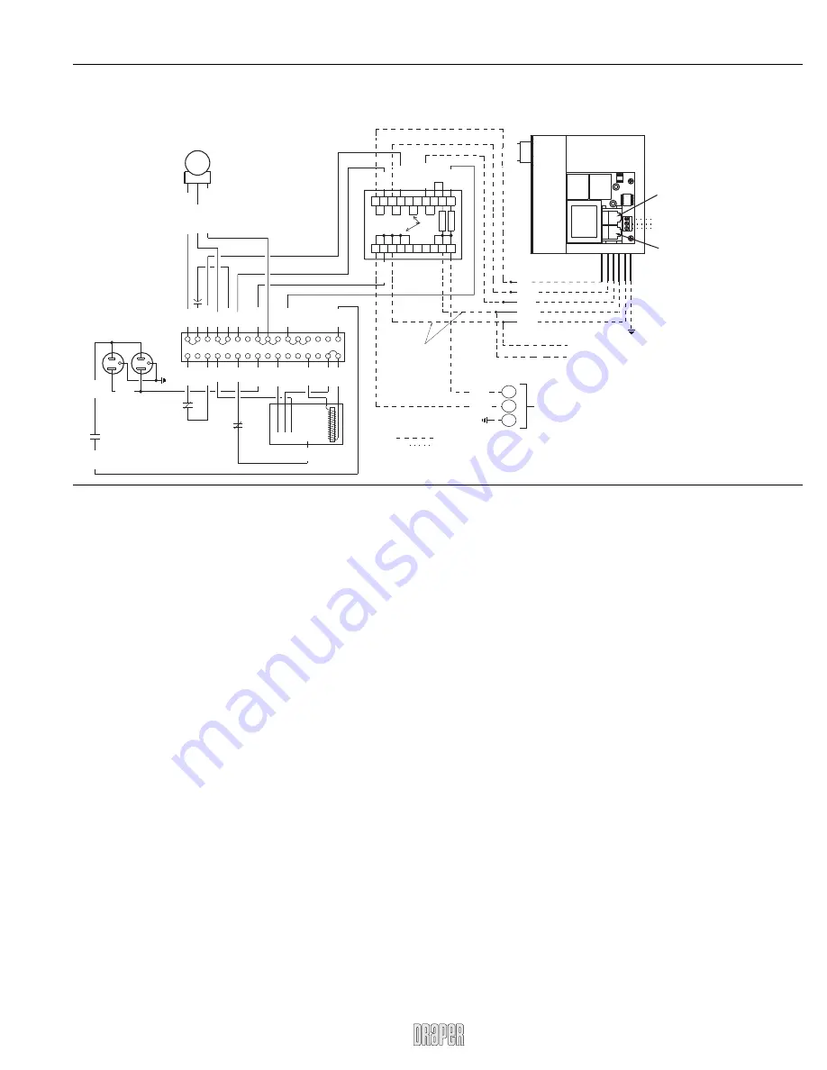
LVC-III—LCD Lift
Wiring Diagram
Alternate Wiring for
Remote Mounting of LVC.
110-120v AC
Supply
Neut
Hot
110-120v AC
Supply
Splice
Red
Brown
Yellow
Black
White
Dashed wiring by electrician
L1
Neu
Grd
Black
White
1 2 3 4 5 6 7 8 9 10
1 2 3 4 5 6 7 8 9 10
Internal Jumpers
Not visible
1A
10A
Red
Ye
llo
w
Blac
k
White
Motor
Blac
k
- Do
wn
Red - Up
White - Neutr
al
Capacitor
Duplex Outlet
Switched on only in
the fully down position
Blac
k
Blac
k
Blac
k
Ye
llo
w
Red
Red
Blac
k
Blac
k
Blac
k
White
1 2 3 4 5 6 7 8 9 10 11 12 13 14 15 16
Blac
k
Blac
k
Blac
k
Blac
k
Blac
k
Red
Red
White
White
White
Green
Receptacle
Limit Switch
LS1 NO
Down Travel
Limit Switch
LS2 NC
Up Travel
Limit Switch
LS3 NC
Blac
k
Red
1 2 3 4 5
AC Current
Sensor
Ye
llo
w
*These can be omitted if LVC is mounted remotely.
*
3 Button Wall Switch
DOWN - Black
COM - White
UP - Red
Green-Ground
Eye Port
for IR Eye, RF Receiver or LED
Switch. If more than one of these three is
used with one LVC-III, a splitter is required.
Aux Port
for connecting additional
LVC-III modules (up to six-
connect from Aux to Eye).
Low voltage wiring by others
Page 3 of 4
LVC-III by Draper
www.draperinc.com
(765) 987-7999


