D
A.
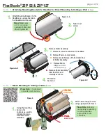
Remove screws from bottom of Headbox.
B.
Remove Fascia and set aside.
C.
Remove Quick Release Pin from Idler End
of Roller Assembly.
Figure 5
Section 3 -
Attaching Mounting Brackets to Headbox for Direct Mounting to Ceiling or Wall
(Optional)
WA
LL
1.
Attach Mounting Brackets to the
Headbox as a spacer between
the Headbox and the wall.
2.
Tighten set
screws.
Section 4 -
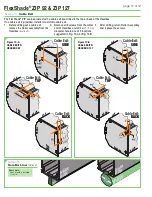
Direct Mounting to Ceiling or Wall
(Optional)
2.
Attach to mounting surface
using appropriate fasteners.
WALL
MOUNT HOLES
CEILING
MOUNT HOLES
1.
Using the mounting
holes in the
endcaps as a guide,
drill pilot holes on
both ends of the
Headbox.
Please Note:
Installer is
responsible for selecting
mounting hardware
appropriate for site
conditions.
B
C
E
A
Figure 4-B
Figure 4-C
3.
Remove Roller Assembly.
4.
Proceed to
Section 4.
Please Note:
Leave
a 1 ¾"
(44mm)
gap
between Endcap and
Mounting Bracket.
Please Note:
If no cable exit
is provided, drill one now.
Figure 4-A
D.
Remove Motor
Clip
(Operator End
of Roller Assembly)
.
E.
Remove Roller Assembly,
Idler End first, and
carefully set aside.
FlexShade
®
ZIP 92 & ZIP 127
page 4 of 12


