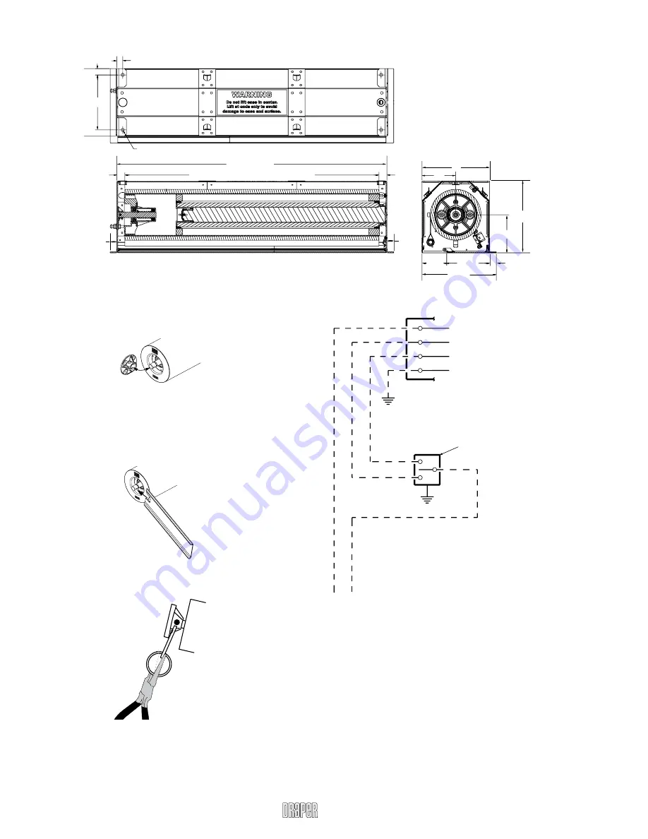
Dimensions
FlexShade 2 with Pocket Headbox by Draper
Page 2 of 2
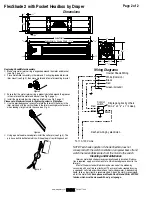
Wiring Diagrams
Internal Shade Wiring
White (Common)
Black
Red
Green (Ground)
Control
switch
Single gang box by others
Min. 4" x 2
1
/
8
" x 1
7
/
8
" deep
Red
Black
Black
To 110-120V Line
Dashed wiring by electrician
www.draperinc.com
(765) 987-7999
NOTE: Test shade operation. If shade direction does not
correspond with the switch orientation, turn power back off and
switch the red and black wires from the motor to the switch.
Cleaning and Maintenance
Idlers on motorized shades may occasionally need lubrication. If lubrica-
tion is required, apply a small amount of a lithium based grease direct to the
idler pin.
Most of Draper’s standard fabrics may be cleaned at the window by
vacuuming with a soft brush attachment. They may also be cleaned by using
a sponge or soft cloth and mild solution of warm soapy water. A dishwashing
liquid, such as Ivory liquid, is recommended. A clean dry cloth is recommend-
ed for the metal finish.
Exceptions are Flocké, Roc-Rol and Phifer SW7000
fabrics, which must be cleaned with a dry art sponge.
Fabric Width = Shade Width - 1
7
/
8
"
Shade Width
15
/
16
"
15
/
16
"
13
/
16
"
4"
4½"
2
15
/
16
"
5
1
/
16
"
8"
8½"
8
13
/
16
"
13
/
16
"
Ø.34"
11
/
16
"
¾"
6½"
13
/
16
"
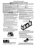
Replacing Shade/Motor Assembly
1
Make sure motor retainer ring is expanded around the motor end bracket
(see Fig. 2, page 1).
2
Place motor/roller assembly in the idler end. Push spring-loaded idler into
idler mount (see Fig. 3), then move motor end into motor mounting bracket.
3
Ensure that the motor retainer ring is properly installed around the grooves
in the motor and the motor end bracket (see Fig. 2, page 1).
4
Install the motor retainer ring screw and tighten (see Fig. 2, page 1).
Please note: Maximum torque for tightening screw is 5 lb-inches.
5
Use the provided spanner wrench to rotate the idler until the holes in the
idler match up with the vertical holes in the idler mounting bracket as seen
when looking straight up into the case (see Fig. 4).
6
Using a pair of needle-nosed pliers install the cotter pin (see Fig. 5). The
pin has a built-in ball detent which will keep the pin from falling back out.
Figure 3
Figure 4
Figure 5


