Caution
1
Read instructions through completely before proceeding.
2
Follow instructions carefully. Installation contrary to instructions invali-
dates warranty.
3
Pick up shade from
ends only
. Picking headbox up at other points
will
damage case
and
may damage fabric
.
4
Entire bottom of shade headbox should be unobstructed to permit
access to bottom panel for making electrical connections or servicing.
5
Shade should be installed level (using a carpenter’s level).
6
Operating switch(es) packed separately in shade carton. Do not
discard with packing material.
7
Shade operates on 110-120V, 60 Hz. current.
NOTE
: Shade has been thoroughly inspected and tested at factory and
found to be operating properly prior to shipment.
Mounting Shade
Regardless of mounting method used, the following points apply:
1
Shade should be lifted into position
only by the end mounting brackets.
Using both mounting holes in mounting brackets makes for a much
more stable installation. Never attempt to lift shade along its length.
2
Shade should be positively and securely supported so that vibration or
even abusive pulling will not weaken installation.
3
Installer must insure that fasteners used are of adequate strength and
suitable for the mounting surface chosen.
Installer must also insure that
wall or ceiling structure are of adequate strength.
Supporting
hardware (chains, cables, rods, etc.) must be essentially vertical.
4
Entire bottom of pocket must be readily accessible after installation is
complete.
5
Front, back and top of pocket must be straight—not forced to warp or bow.
Adjust spreader bars to keep large cases from warping.
6
Do not use pocket to support adjacent sections of ceiling.
7
If optional ceiling flange trim kits are attached, use hardware provided.
8
If pocket is painted, slots on bottom of case should be shielded to protect
viewing surface from paint splatters or overspray.
Caution
: Shade is shipped with motor wiring mounted to the headbox. Be
careful not to pull the wiring loose from the headbox while removing the
brackets—if wiring is loose, it could be damaged during shade operation. If
wiring does come loose, re-mount as it was.
9
Do not seal unit in ceiling until electrical connections have been made and
shade has been operated successfully.
Electrical Connections
Shade operates on 110-120V, 60 Hz. current.
Shade is shipped with internal wiring complete and control switch(es) fully
boxed. Wire connecting shade to switch(es) and switch(es) to power supply
should be furnished by installer. Connections should be made in accordance
with attached wiring diagram, and wiring should comply with national and
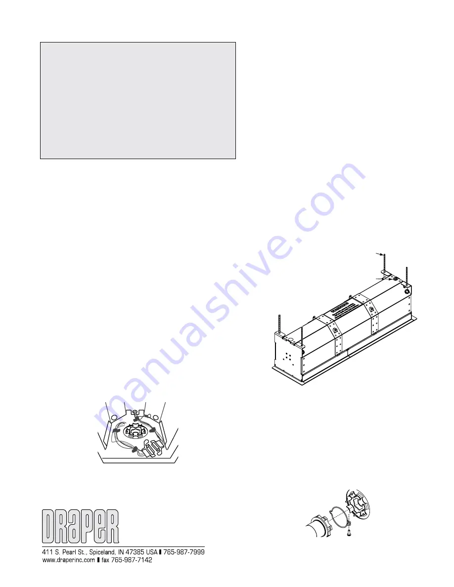
local electrical codes. See Fig. 1 for internal view of wiring.
All operating switches should be “off” before power is connected.
Please Note:
For low voltage wiring requirements, Draper recommends con-
sulting with a professional low voltage electrical contractor. It is very important
that shielded and stranded CAT 5 cable be used to prevent any electrical
interference.
Operation
When shade is first operated,
be cautious!
Cycle unit down and up several
times to confirm satisfactory operation.
Adjustments
Shade has been factory set and should not normally require further
adjustment. However, if you desire to change the “up” and “down” stopping
positions, proceed as follows:
CAUTION:
Be sure all switches are in “off” position before adjusting
limit switches. Always be prepared to shut shade off manually when new
adjustment is being tested. Shade may be severely damaged if allowed to run
too far up or too far down.
ADJUSTING “FULLY UP” POSITION
—Put a small screw driver in the groove
of the yellow button on the motor and press vertically until hearing a "click".
Raise the shade by pressing the "up" switch on unit. Press the "stop" switch
when the shade is at the desired position. Then press the yellow button on
motor until you hear a "click", then release.
ADJUSTING “FULLY DOWN” POSITION—
Put a small screw driver in the
groove of the white button on the motor and press vertically until hearing a
"click". Lower the shade by pressing the "down" switch on unit. Press the
"stop" switch when the shade is at the desired position. Then press the white
button on motor until you hear a "click", then release.
AT NO TIME SHOULD SHADE BE UNROLLED ENOUGH TO EXPOSE ANY
PART OF SHADE ROLLER.
Please Note:
The above instructions affect only the limits on the motors. For
adjustment procedures using Draper’s IntelliFlex Control Systems, please
consult the installation information for the appropriate control.
Installation/Operating Instructions
FlexShade 2 with Pocket Headbox by Draper
Copyright © 2016 Draper Inc. Form FlexShade2_PocketHB_Inst16 Printed in U.S.A.
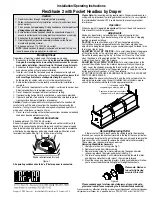
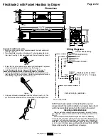
Please see back page for dimensional diagrams of case, wiring dia-
grams and instructions on replacing the roller/roller/fabric assembly.
If you encounter any difficulties installing or servicing your FlexShade 2 with Pocket Headbox,
call your dealer or Draper, Inc., Spiceland, Indiana, (765) 987-7999 or fax (765) 987-7142.
Knockouts for electrical connections
(three per end) with plastic plugs
5
/
16
" threaded rod (for
suspending shade) by others.
Shade roller removed for clarity
Figure 1
Removing/Replacing Roller
If there is not sufficient access above the ceiling to get to the mounting
brackets, you can use the knockouts located in the top of the case just below
the mounting bracket holes. To get to these holes, you will need to remove the
hole covers. You will also need to remove the shade motor/roller assembly.
These steps may require more than one person.
Removing Shade/Motor Assembly
1
Unplug motor from unit wiring (see Fig. 1).
2
Remove cotter pin from idler assembly.
3
Remove locking screw from motor retainer ring, then expand motor
retianer ring around the motor-end bracket (see Fig. 2).
4
The idler is spring-loaded. Push motor/roller assembly toward the idler
end. Remove motor from motor mount, then remove idler end.
5
Mount the case using mounting brackets. A long-handled driver will allow
you to access the bracket mounting holes through the knockouts.
Please note: Maximum
torque for tightening
screw is 5 lb-inches.
Figure 2


