


220V Access MultiView by Draper
page 3 of 4
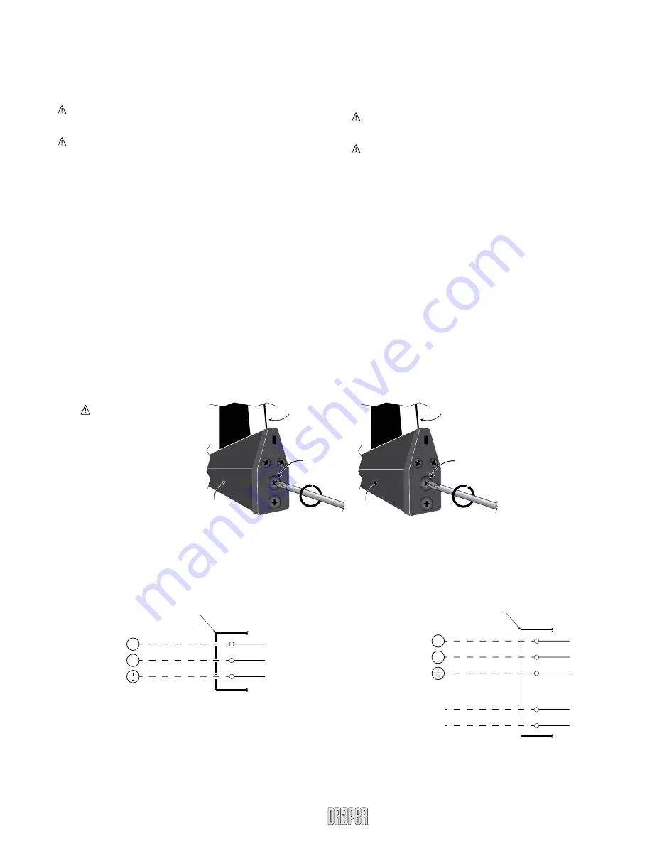
Wiring Diagrams for Optional Built-in Controls
Adjustments (Screen Motor)
Please Note: Screen limits are factory set for optimum performance of
the screen. A procedure is outlined below for minor tweaks, but any
adjustment of these limits may negatively affect the flatness of the
screen surface and could also void the warranty. Please check with
Draper prior to resetting screen limits.
CAUTION: Always be prepared to shut screen off manually when new
adjustment is being tested. Screen may be severely damaged if viewing
surface is allowed to run too far up or too far down.
C
AUTION: Be sure all switches are in “off” position before adjusting
limit switches.
“DOWN” LIMIT SWITCH
—Down stopping position can be adjusted by turn-
ing the white socket (located on the motor end of screen roller). Turning the
socket counterclockwise will allow the roller to run farther down. Turning it
clockwise will shorten operation, causing it to stop sooner. One full revolution
of the socket will alter the stopping position of the viewing surface by approxi-
mately 32 mm.
“UP” LIMIT SWITCH—
Up stopping position can be adjusted by turning the
yellow socket (located on motor end of screen). Turning the socket counter-
clockwise will allow the roller to run farther up. Turning it clockwise will cause
the roller to stop sooner. One full revolution of the socket will alter the stopping
position of the viewing surface by approximately 32 mm.
AT NO TIME SHOULD SURFACE BE UNROLLED ENOUGH TO EXPOSE
ANY PART OF SCREEN ROLLER.
If you encounter any difficulties installing or servicing your Access MultiView
screen, call your dealer or Draper, Inc., Spiceland, Ind., (765) 987-7999 or fax
(765) 987-1689.
Adjustments (Masking Motor)
Please Note: Screen limits are factory set for optimum performance of
the screen. A procedure is outlined below for minor tweaks, but any
adjustment of these limits may negatively affect the flatness of the
screen surface and could also void the warranty. Please check with
Draper prior to resetting screen limits.
CAUTION: Always be prepared to shut screen off manually when new
adjustment is being tested. Screen may be severely damaged if viewing
surface is allowed to run too far up or too far down.
C
AUTION: Be sure all switches are in “off” position before adjusting
limit switches.
“DOWN”
LIMIT SWITCH—Down stopping position can be adjusted by turning
knob #2 (on motor end of masking roller). Turning the knob counterclockwise
will allow the roller to run farther down. Turning it clockwise will shorten opera-
tion, causing it to stop sooner.
“UP” LIMIT SWITCH—
Up stopping position can be adjusted by turning knob
#1 (on the motor end of masking roller). Turning the knob counterclockwise
will allow the roller to run farther up. Turning it clockwise will cause the roller to
stop sooner.
Built-in Video Interface Control
Junction box at
left end of screen
Internal screen wiring
White (Neutral)
Black (Hot)
Green (Ground)
Dashed wiring
by electrician
220V AC supply
Trigger signal
VIC220 (220 V AC, white cord & plug)
VIC12 (12 VDC, brown & orange leads)
N
L1
Built-in Low Voltage Control
Junction box at
left end of screen
Internal screen wiring
White (Neutral)
Black (Hot)
Green (Ground)
Dashed wiring
by electrician
220V AC supply
N
L1
www.draperinc.com
(765) 987-7999
C
OU
NTER-CLO
CK
W
IS
E
ADJUSTMENT
SCREW
TENSIONING
CABLE
DOWEL
TO
RE
LEASE TEN
SIO
N
T
U
R
N
CLOCKW
IS
E
ADJUSTMENT
SCREW
TENSIONING
CABLE
DOWEL
TO
IN
CREASE TEN
SIO
N
T
U
R
N
Tab-Tension Adjustment Procedure
Draper’s Tab-Tensioning System is factory-set, and under normal circumstances will not require field adjustment.
If, however, you notice wrinkles, waves or other indications that the tensioning cables need to be adjusted, follow the procedure below.
1
Determine which side requires adjustment.
2
Secure dowel with one hand.
3
Using Phillips-head screwdriver, depress spring-loaded adjustment screw and slowly turn
CLOCKWISE TO INCREASE
tension,
or
COUNTER-CLOCKWISE TO RELEASE
tension. The screw adjusts in ¼ turn increments. Adjust only
one increment
(¼ turn) at a time
4
If problem is not corrected, leave screen in position for 24 hours to allow surface material to stretch into position.
5
If problem still is not corrected, repeat steps 2 and 3.
Caution: Do not touch
or bend surface.


