background image

- 7 -

ASSEMBLY INSTRUCTIONS

Assembly of the mower

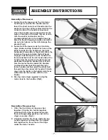
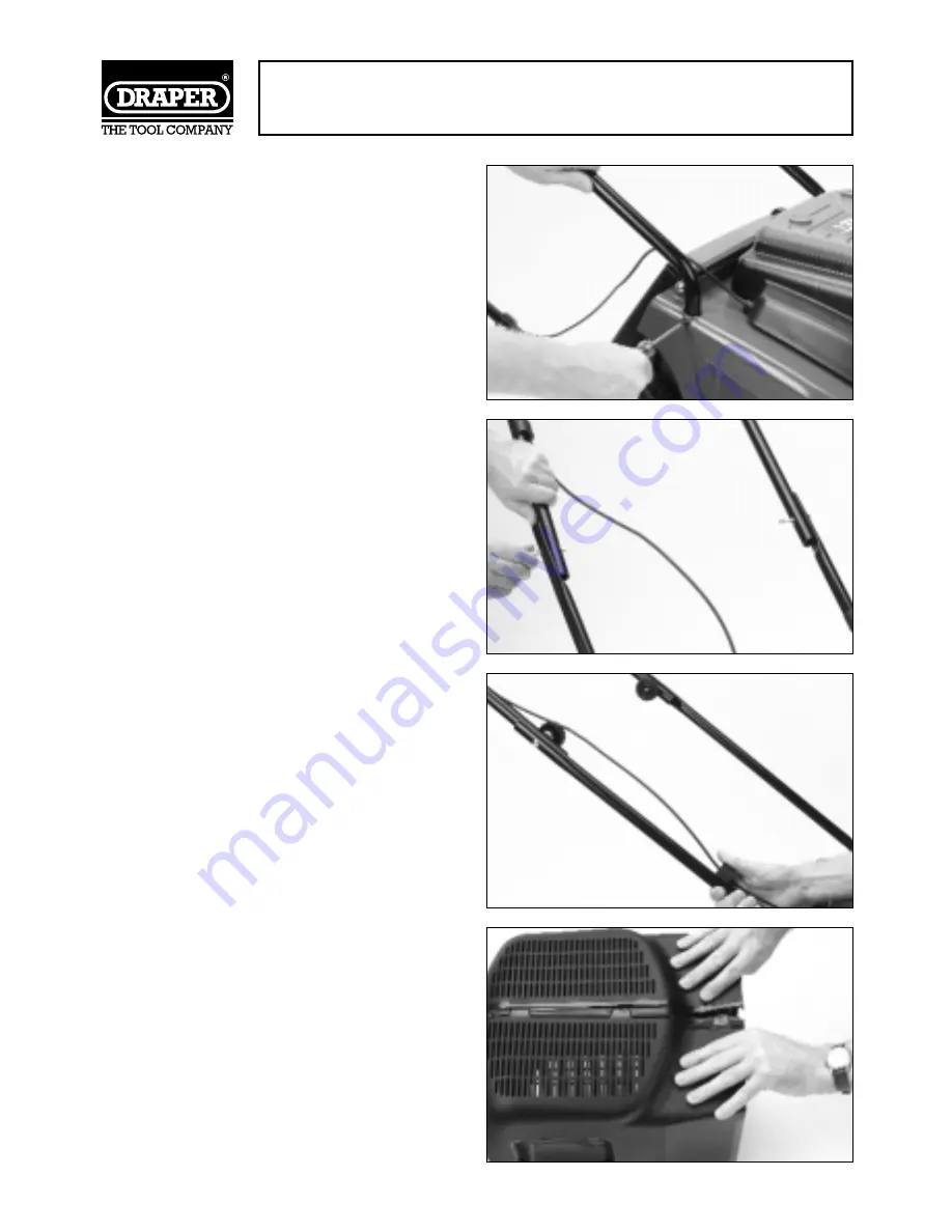
1. Locate from the loose parts the two lower

handle parts and the two handle screws.

Insert the short end of each handle into the
sockets at the rear of the mower deck so the
concave side of the handle is innermost.

Once the handles are positioned locate the
holes in the side of the deck that are in line
with the socket and make sure the
corresponding hole in the handle lines up.
Screw in the self tapping handle screws but
do not over tighten as this will damage the
plastic.(Fig.1).

2. Locate from the loose parts the two bolts,

caps, knobs and top handle. Push one of the
bolts through the top handle on the right
hand side (same side as the switch) from the
inside so the square under the bolt head
engages with the square in the handle. Put
the second bolt into the left hand side of the
handle from the inside so the bolt only just
protrudes through the handle (Fig.2). Make
sure the motor lead is inside the handles
and feed the first bolt through the right
lower handle and then push the other bolt
through the other lower left handle. Fit both
caps onto the bolts so the hollow side faces
outwards and then secure with the two
knobs.

3. Use the cable clips supplied to clip the

motor lead to the handles (Fig3).

Assembly of the grass box

1. Offer the two halves of the grass box

together. Clip the two halves together
ensuring that all the tongues locate into
their corresponding grooves and all the
clips are secure (Fig.4).

2. Carefully fold the two flaps under the top

handle together making sure the fingers
knit together. Do the same for the flaps
under the lower handle.

Fig.1

Fig.2

Fig.3

Fig.4

Summary of Contents for 64097

Page 1: ...fe use We recommend that this manual is read before any operation of the machine before performing any kind of adjustment to the machine and prior to any maintenance tasks By following all the general safety instructions contained in this manual it will ensure both machine and operator safety together with longer life of the tool itself All photographs and drawings in this manual are supplied by D...

Page 2: ...tions 8 Charging the Battery 9 Changing the Blade 10 Maintenance and Trouble Shooting 11 Optional Accessories 12 We Draper Tools Ltd Hursley Road Chandler s Ford Eastleigh Hampshire SO53 1YF England Declare under our sole responsibility that the product Stock Nos 64097 Part Nos LM12 Description Cordless Lawn Mower To which this declaration relates is in conformity with the following directive s 98...

Page 3: ...ol develop any fault please return the complete tool to your nearest authorised warranty repair agent or contact Draper Tools Limited Chandler s Ford Eastleigh Hampshire SO53 1YF England Telephone 023 8026 6355 If upon inspection it is found that the fault occurring is due to defective materials or workmanship repairs will be carried out free of charge This guarantee does not apply to normal wear ...

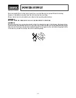
Page 4: ...nformation WARNING BATTERY MUST BE CHARGED FOR 24 30 HOURS PRIOR TO FIRST USE CAUTION This lawn mower has a sealed lead acid battery that should be kept at full charge Recharge when first received immediately after each use and every three months if not used Immediately charge when the unit has been incorrectly overdischarged Do not operate the unit while charging Failure to do this may cause the ...

Page 5: ... as cutters etc 16 AVOID ACCIDENTAL STARTING Make sure the switch is in the OFF position before plugging the machine into the power supply 17 NEVER LEAVE MACHINE RUNNING UNATTENDED Turn power off Do not leave machine until it comes to a complete stop 18 DO NOT ABUSE THE CORD Never carry the tool by the power cable or pull it from the socket Keep the power cable away from heat oil and sharp edges 1...

Page 6: ...ne the blade and nut for damage Repair or replace any damaged parts before restarting and operating the mower 15 Always disconnect your mower from the power supply before lifting or carrying 16 Stop the blade if the mower has to be tilted up for transportation when crossing surfaces other than grass 17 Do not tilt the mower when starting the motor The only exception is when the mower will not star...

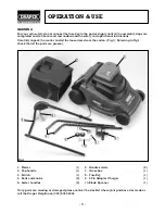
Page 7: ...ack the mower and all the loose items from the carton Fig 1 Referring to Fig 1 check that all the parts are present 1 Mower 1 2 Top handle 1 3 Switch 1 4 Bolts and knobs 2 5 Lower handles 2 6 Handle screws 2 7 Grass box 1 8 Fuse Key 1 9 3 Pin Adapter Charger 1 10 Blade Spanner 1 If any parts are missing or damaged please contact the stockist where your purchase was made or call the Draper Helpline...

Page 8: ...square under the bolt head engages with the square in the handle Put the second bolt into the left hand side of the handle from the inside so the bolt only just protrudes through the handle Fig 2 Make sure the motor lead is inside the handles and feed the first bolt through the right lower handle and then push the other bolt through the other lower left handle Fit both caps onto the bolts so the h...

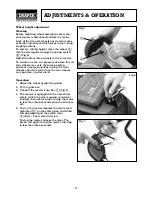
Page 9: ...on however in some situations having the front wheels one notch lower than the rear wheels may produce a better result Operation 1 Adjust the wheel height if required 2 Fit the grass box 3 Connect the mower Fuse Key Fig 6 4 The mower is equipped with an electrical safety switch to protect against accidental starting and a motor brake to stop the motor in less than three seconds once the switch is ...

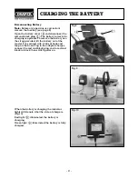
Page 10: ...ttery use the strap provided lift the battery out of the mower It is secured with 2 tabs of hook and loop on the base Plug in the adaptor charger connect the red and black plug red to red and black to black then switch power on When the battery is charging the indicator lights will denote what the state of charge is Fig 10 Red light illuminated the battery is charging Green light illuminated the b...

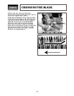
Page 11: ...ing the sharp edges Grip the blade with a gloved hand and using the wrench supplied undo the centre nut in an anticlockwise direction remove the nut and two locating plates then the blade To replace the blade follow these instructions in reverse making sure the wing on the back of the blade is angled upwards when fitted on the mower and the mower on it s wheels Fig 12 Fig 11 Fig 12 ...

Page 12: ...ade rotates is there some friction due to the brake If the blade does not move contact a service repair agent Mower vibrates in use Stop using immediately Disconnect the mowers fuse key from the power supply with the blade stopped check to see if the blade bolt is loose tighten if necessary see page 10 If the blade bolt is already tight contact a service repair agent Mower does not pick up the gra...

Page 13: ... 12 OPTIONAL ACCESSORIES Part No AGP15 Stock No 64553 Description Spare Blade Part No YLM12 Stock No 64560 Description Fuse Key ...

Page 14: ...NOTES 13 ...

Page 15: ...NOTES 14 ...

Page 16: ...26 6355 Fax 023 8026 0784 www draper co uk e mail sales draper co uk Published by Draper Tools Ltd No part of this publication may be reproduced stored in a retrieval system or transmitted in any form or by any means electronic mechanical photocopying recording or otherwise without prior permission in writing from Draper Tools Ltd YOUR DRAPER STOCKIST ...

Reviews: