background image

WOODTURNING OPERATIONS cont’d

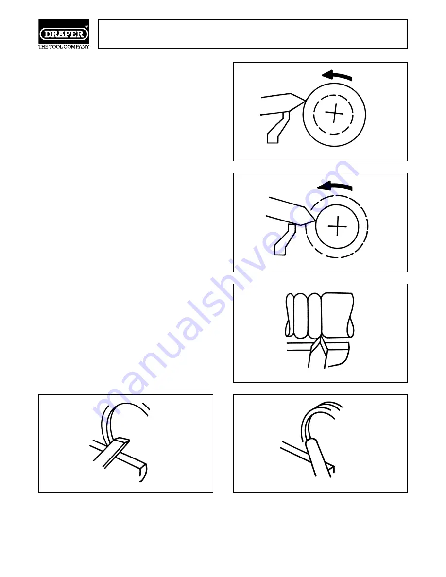
USING A PARTING CHISEL

A parting chisel has one primary purpose – to cut
straight into the workpiece as deep as desired, or all
the way through the workpiece to make a cut off. This
is a very narrow chisel approximately 

1

8

wide and is

shaped to cut its own clearance, so the cutting edge
will not burn. But when used as a scraper, it should
be backed off at regular intervals to prevent
overheating. See Figs. 53 and 54.

USING SCRAPING CHISELS

Finally, three more types of chisel should complete
the list of chisels for the average craftsman, these
and 

1

2

spear point, 

1

2

round nose and a 1

flat node.

Each of these chisels may be purchased in various
sizes, (refer to the Draper Catalogue) for special
jobs. All of these are very useful for diameter
scraping (see Figs. 55, 56 and 57) operations and for
circumference scraping, when cutting methods
cannot be employed.

The spear point chisel is used for fine scraping and
delicate operations such as the forming of beads,
parallel grooves and shallow vees. Edges and bowl
contours can be rounded with the round nose chisel.
Any flat surface can be scraped with the flat nose
chisel.

- 21-

Fig.53.

Fig.54.

Fig.55.

Fig.57.

Fig.56.

CUTTING

SCRAPING

SPEAR POINT

FLAT NOSE

ROUND NOSE

Summary of Contents for 55951

Page 1: ...WOOD LATHE INSTRUCTIONS IMPORTANT PLEASE READ THESE INSTRUCTIONS CAREFULLY TO ENSURE THE SAFE AND EFFECTIVE USE OF THIS TOOL MODEL WTL30 STOCK No 55951 08 99 ...

Page 2: ...g 6 Assembly installation 7 11 Wood lathe adjustments 12 Woodturning operations 13 14 Using woodworking chisels 15 21 Optional accessories 22 Trouble shooting 23 VARIABLE SPEED WOOD LATHE MODEL WTL30 STOCK No 55951 We Draper Tools Ltd Hursley Road Chandlers Ford Eastleigh Hampshire SO53 1YF England Declare under our sole responsibility that the product Part Number WTL30 Stock Numbers 55951 Descrip...

Page 3: ...er any damage caused by misuse careless or unsafe handling alterations accident or repairs attempted or made by any personnel other than the authorized Draper warranty repair agent This guarantee applies in lieu of any other guarantee expressed or implied and variations of its terms are not authorized Your Draper guarantee is not effective unless you can produce upon request a dated receipt or inv...

Page 4: ...hazardous if engaged in a live power socket outlet WARNING THIS APPLIANCE MUST BE EARTHED Green and Yellow Earth Blue Neutral Brown Live As these colours may not correspond with the coloured markings identifying the terminals in your plug proceed as follows The wire which is coloured green and yellow must be connected to the terminal in the plug which is marked with the letter E or by the earth sy...

Page 5: ...s cutters etc 16 AVOID ACCIDENTAL STARTING Make sure the switch is in the OFF position before plugging the machine into the power supply 17 NEVER LEAVE MACHINE RUNNING UNATTENDED Turn power off Do not leave machine until it comes to a complete stop 18 DO NOT ABUSE THE CORD Never carry the tool by the power cable or pull it from the socket Keep the power cable away from heat oil and sharp edges 19 ...

Page 6: ...EPLATE Provides information such as Model No Stock No Serial No Specification etc DRIVE BELT MOTOR PULLEY 5 speed manual change ON OFF SWITCH No volt overload protection TOOL REST CLAMPING BRACKET TOOL REST LOCK HANDLES Locks tool rest in required position BED Supports tailstock toolrest TAILSTOCK ADJUSTMENT WHEEL TAILSTOCK ADJUSTMENT LOCKING HANDLE Locks tailstock barrel in position LIVE CENTRE A...

Page 7: ...ood lathe on the workbench stand before drilling location holes this will ensure a totally correct alignment Mark and drill two 9 5mm 3 8 holes Fig 2 in the top of the workbench stand as shown in Fig 2 Ensure the headstock is positioned so you do not drill into the legs or support rails underneath Call the Power Division Helpline 01703 494344 if you have any enquiries eg problems with assembly app...

Page 8: ...eads but do not tighten Fig 5 Align the two keys Fig 6 the strips of metal bar fastened to each bed half by the screws with each other so they are exactly in line This alignment is necessary so that the tailstock assembly and tool rest base assembly will slide freely over the joint between the two halves Align the bed half keys by placing a metal straight edge against one side of the keys Now slid...

Page 9: ...ral turns and reposition the foot being very careful not to disturb the key alignment Retighten bolt Securing the bedfoot to the workbench or stand When you are satisfied the wood lathe is correctly set up mark on the workbench stand the two locating holes in the foot Fig 9 and drill two 9 5mm 3 8 holes in the workbench stand Insert two 5 16 x 2 bolts through the holes in the foot Place a flat was...

Page 10: ...ock spindle and the live centre into the tailstock barrel as shown in Fig 12 NOTE Do not drive or hammer centres into the headstock spindle or tailstock barrel as removal may be difficult Use a soft faced hammer block of wood or gently tap them using a small hammer and piece of softwood as shown in Fig 12 REMOVAL To remove the drive spur from the headstock spindle hold the spindle pulley Fig 13 Wi...

Page 11: ...ed when locked down without damaging the bed Locate the two brass slugs from the loose parts supplied Insert a brass slug into the threaded hole of tailstock Fig 17 and into tool rest not shown and screw the lock handles into the holes until tight Now screw the other two clamping handles into their locating holes ALIGNMENT OF TAILSTOCK CUP CENTRE TO HEADSTOCK DRIVE SPUR The drive spur and live cen...

Page 12: ...otor pulley Now rotate the spindle pulley clockwise with your right hand while pushing on the belt with your left hand The belt will climb up to the next step of the the spindle pulley or rotate the spindle pulley clockwise with your right hand and pull on the belt whilst still rotating the pulley until it climbs down to the next step Now rotate the motor pulley anti clockwise with your left hand ...

Page 13: ...end Make sure the spurs are in the saw cuts and remove the drive spur Ensure that both the drive spur and live centre are clean Insert the drive spur into the headstock and the live centre into the tailstock tap them lightly with a piece of wood DO NOT DRIVE THEM IN Ensuring the diagonally cut end is against the drive spur place the piece of wood between the centres and lock the tailstock See Fig ...

Page 14: ...rning can be divided in the same way WARNING THE INDEXING PIN MUST BE DISENGAGED FOR ALL OTHER OPERATIONS OUTBOARD TURNING This technique would be used when the workpiece is too large to mount conventionally It is the same as standard face plate turning except that because of the size of the workpiece the turning speed should be kept to a minimum If you intend outboard turning you must build a sta...

Page 15: ...craping are left on to aid in the scraping process Fig 31 shows the two types of chisel CUTTING AND SCRAPING To make a cut the chisel should be held so that the sharp edge actually digs into the revolving workpiece shavings should now peel off To scrape the chisel should be held at a right angle to the surface of the workpiece fine pieces of wood will be produced when scraping instead of shavings ...

Page 16: ...ds the circumference the shaving will come off like the peel from a potato Only scraping can be used when the method used is towards the diameter The reason for this is obvious when you consider that faceplate turning nearly always requires the removal of wood across the grain Wood does not peel easily when turning across the grain and any attempt made to use cutting methods will probably result i...

Page 17: ... into the workpiece until the bite becomes so deep that you have difficulty holding the chisel then the chisel will begin to bounce or chatter against the workpiece If the tool rest is positioned too low the chisel will be held extremely high to position the bevel of the chisel against the workpiece as shown in Fig 36 then the tool rest will lose its value as a fulcrum and the downward force of th...

Page 18: ...er to the surface workpiece than normal As the workpiece gets smaller the rest should be repositioned as shown in Fig 40 POSITIONING THE TOOL REST FOR CIRCUMFERENCE SCRAPING When scraping the position of the tool rest is not as critical as it is for cutting operations The chisel is normally held horizontally although it can be held at an angle to reach difficult places The wire edge of the chisel ...

Page 19: ...ition in which it is easiest to hold the chisel steady To obtain the position place the rest approximately 1 8 below the centre USING A GOUGE CHISEL Three gouges 1 4 1 2 and 3 4 sizes are usually sufficient for home workshop turning but other sizes are available refer to the Draper Catalogue A gouge chisel is normally used for rough circumference turning or turning raw stock down to a cylinder of ...

Page 20: ...hould be held with the cutting edge considerably in advance of the handle and should be bevel side down Always keep the base of the bevel against the work Good practice is to place the skew well over the workpiece and pull it back until the edge begins to cut then swing the handle into position to advance the cut Both the tow and the heel of the skew can be used for making light cuts but do not pe...

Page 21: ...ete the list of chisels for the average craftsman these and 1 2 spear point 1 2 round nose and a 1 flat node Each of these chisels may be purchased in various sizes refer to the Draper Catalogue for special jobs All of these are very useful for diameter scraping see Figs 55 56 and 57 operations and for circumference scraping when cutting methods cannot be employed The spear point chisel is used fo...

Page 22: ...29422 Cup turning chuck Part No AWL2 Stock No 29423 Screw chuck Part No AWL3 Stock No 29424 Left hand thread face plate Part No AWL6 Stock No 29427 Right hand thread face plate Part No AWL8 Stock No 29429 Combination chuck Part No AWL40 Stock No 37168 Face shield Part No FS8 Stock No 33831 Turning chisel hobby set Part No AWL5 Stock No 29426 For a comprehensive range of wood lathe accessories refe...

Page 23: ...chnician 3 Blown fuse 3 Replace fuse Lathe slows down 1 V belt too loose 1 Adjust belt tension see Belt Tension when turning Page 12 G3 Tailstock rocks back 1 Adjusting screw is too loose 1 Adjust screw See Assembly Section and forth excessively Page 11 F15 Headstock loose on bed 1 Set screw not tight 1 Tighten set screw See Assembly Section Page 9 F8 Wood burns at tailstock 1 Live centre too tigh...

Page 24: ...x 01703 260784 YOUR DRAPER STOCKIST Published by Draper Tools Ltd No part of this publication may be reproduced stored in a retrieval system or transmitted in any form or by any means electronic mechanical photocopying recording or otherwise without prior permission in writing from Draper Tools Ltd ...

Reviews: