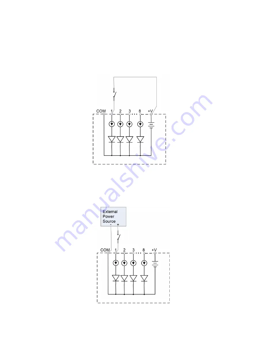
Dranetz HDPQ-DN-MZP Quick Reference Manual Download Page 35

35 

Internal Supply  


Each channel 1 through 8 is referenced to the “COM” 
terminal. 

Individual channels can be connected between the 
“COM” to the “ – “ terminal of your monitoring source 
which serves as the reference. Each “+” terminal 
(1,2,3,4,5,6,7,8) of the instrument connects to the “+” 
terminal of your monitoring source. 


External Supply  


If an external voltage supply is used instead of the +V 
output, the “COM” terminal must be connected to the 
external common of the digital power source. 


Summary of Contents for HDPQ-DN-MZP

Page 1: ...nce Guide HDPQ DataNode with Voltage Current Pod Connectors Dranetz Model HDPQ DN MZP Dranetz 1000 New Durham Road Edison New Jersey 08818 Telephone 1 800 372 6832 or 732 287 3680 Fax 732 248 1834 www...

Page 2: ...fety training on the hazards involved Qualified personnel who work on or near exposed energized electrical conductors must follow applicable safety related work practices and procedures including appr...

Page 3: ...ado ANSI NFPA 70E 2015 de los E E U U y cualquier requisito de seguridad adicional del lugar de trabajo aplicable a su instalaci n AVERTISSEMENT Si l instrument est mal connect la mort des blessures g...

Page 4: ...zugeh rigen Gefahren vertraut ist Qualifiziertes Personal das an bearbeiten oder herausgestellte angezogene elektrische Leiter sich n hern mu anwendbare Sicherheit bezogener Arbeit Praxis und Verfahre...

Page 5: ...trument on live power lines Connections must be made to the instrument first then connect to the circuit to be monitored Wear proper personal protective equipment including safety glasses and insulate...

Page 6: ...king Measurement Connections 21 Connecting the Voltage and Current Input Pods 22 Connecting the Input Pods to the HDPQ DataNode 24 Single Phase 26 Split Phase 27 3 Phase Four Wire Wye 28 3 Phase Float...

Page 7: ...also supported The HDPQ DN MZP allows you to customize threshold settings for power quality energy and demand It can monitor power quality and energy demand phenomena for troubleshooting and or compl...

Page 8: ...nput stated on the unit nameplate can cause damage to the unit La operaci n del HDPQ DataNode desde una fuente de voltaje de ca que no sea la entrada de voltaje nominal indicada en la placa de identif...

Page 9: ...is found at the rear panel of the unit The rear panel for DataNode Model HDPQ DN MZP is shown below Power Source The rear panel marking provides information about the input power rating Voltage range...

Page 10: ...ss of power the unit will seamlessly switch to the internal battery backup and will switch back to the normal power source when restored Front Panel The front panel shows the following three 3 LED ind...

Page 11: ...ults See section Reset to Factory Defaults for details on how to manually reset the instrument to factory configuration Power Switch use to turn unit power on or off Power indicator lamp on front pane...

Page 12: ...the rear panel of the HDPQ DataNode Press in the internal reset button and hold for ten 10 seconds Continue to hold until the Status LED indicator at the front panel stops blinking which indicates tha...

Page 13: ...stablish communications with the server software Refer to the procedures in the next sections to connect to the HDQP DataNode to change communication and other settings In order to connect to the HDPQ...

Page 14: ...the rear panel to turn the instrument ON 4 In order to complete the Ethernet connection the computer IP address needs to be changed to be in the same range as the HDPQ DataNode address Once the compu...

Page 15: ...isplayed Click the Commissioning Setup tab and select Ethernet Setup Result The following screen is displayed 7 On the Commissioning Setup Ethernet Setup screen enter the applicable setting changes an...

Page 16: ...ed connection first to enable and to set up the WiFi connection to the instrument Refer to the previous section Connecting via Wired Ethernet Connection on page 14 and follow Steps 1 to 5 Once the HDP...

Page 17: ...ect from the available WiFi networks on the dropdown menu and then click on the NEXT button to the right 6 Provide the required credentials for the WiFi network you are connecting to Wireless network...

Page 18: ...irements Operating System Category 5e Cable Internet Browser Windows 10 Windows 8 Professional Standard RJ45 connector cross over cable Not Included Internet Explorer 11 x Edge Firefox etc Follow thes...

Page 19: ...address 5 Click on the Get button to populate the left fields with your HDPQ Ethernet Settings Result The following screen opens 6 If you wish to change any of the setting you can edit the field and...

Page 20: ...20 Once the HDPQ DataNode is set up connect to the instrument to verify the settings NOTE You may have to change the Internet settings on your computer to connect...

Page 21: ...de instalaci n y operaci n durante el uso de este instrumento AVERTISSEMENT Si l instrument est mal connect la mort des blessures graves ou un danger d incendie peuvent s en suivre Lisez attentivement...

Page 22: ...voltage signals that can be measured by the DataNode All connections are safety terminated by the pod therefore the DataNode can be safely removed The protective earth ground of the HDPQ DataNode main...

Page 23: ...the edge 4 Route power wires in a safe manner in accordance with good practice and local codes 5 Connect the ground wire first before making any other connections 6 Connect power source to the Voltag...

Page 24: ...24 Connecting the Input Pods to the HDPQ DataNode...

Page 25: ...puts Fuses must be located as close to circuit connection as possible to maximize protection For continued protection against risk of fire or shock hazard replace only with same type and rating of rec...

Page 26: ...eutral to Ground voltage and Neutral currents Neutral to ground measurements are important but optional CAUTION Connections must be performed in compliance with all safety requirements applicable to y...

Page 27: ...s monitoring the Neutral to Ground voltage and Neutral currents Neutral to ground measurements are important but optional CAUTION Connections must be performed in compliance with all safety requiremen...

Page 28: ...oring the Neutral to Ground voltage and Neutral currents Neutral to ground measurements are important but optional CAUTION Connections must be performed in compliance with all safety requirements appl...

Page 29: ...ase B C and channel C monitoring phase C A Current inputs are connected to measure line currents A B and C CAUTION Connections must be performed in compliance with all safety requirements applicable t...

Page 30: ...t inputs A and C are measured by the instrument using voltage and current inputs A and B CAUTION Connections must be performed in compliance with all safety requirements applicable to your installatio...

Page 31: ...rent sources The neutral is connected to common and is the reference for the three channels CAUTION Connections must be performed in compliance with all safety requirements applicable to your installa...

Page 32: ...rent sources The neutral is connected to common and is the reference for the three channels CAUTION Connections must be performed in compliance with all safety requirements applicable to your installa...

Page 33: ...w Terminal 5537APOD POD 5A 5X 4 Channel External Interface Wire Passthru 5532APOD POD 5A 20X 4 Channel External Interface Wire Passthru 5533APOD POD 1A 5X 4 Channel External Interface Screw Terminal 5...

Page 34: ...voltage level goes below 1 0 volts The maximum input signal level is 200VDC All logic transitions are time stamped to the millisecond and available for simultaneous comparison to all other data colle...

Page 35: ...the terminal of your monitoring source which serves as the reference Each terminal 1 2 3 4 5 6 7 8 of the instrument connects to the terminal of your monitoring source External Supply If an external...

Page 36: ...Environmental Operating 0 to 55 C 32 to 131 F Storage 40 to 70 C 40 to 158 F Humidity 5 to 95 non condensing Altitude 2000m 6560 ft maximum Installation categories Mains supply Installation Category I...

Page 37: ...for a period of one year from the date of invoice Warranties for products and accessories sold by but not branded as Dranetz are covered by their respective manufacturer s warranties and are not warra...

Page 38: ...area is likely to cause harmful interference in which case the user will be required to correct the interference at his her own expense Notice Regarding Proprietary Rights This publication contains in...

Page 39: ...39 This page intentionally left blank...

Page 40: ...40...

Reviews: