background image

Quick Reference Guide for PowerXplorer / Power Guide / Power Visa


pg 26 


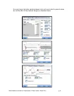
The wizard uses interactive graphical images to show the user what the present values 
are and the effect of the proposed changes, as illustrated below. 


Summary of Contents for Power Guide 4400

Page 1: ...POWER VISA A quick reference guide for the PowerXplorer Power Guide Power Visa product family It is recommended that the user still be familiar with the complete User s Guides for the respective products as it contains more detailed information about all of the functions as well as the specifications and accessories ...

Page 2: ...ns and who has received safety training on the hazards involved Qualified personnel who work on or near exposed energized electrical conductors must follow applicable safety related work practices and procedures including appropriate personal protective equipment in compliance with the Standard for Electrical Safety Requirements for Employee Workplaces ANSI NFPA 70E 2004 of USA and any additional ...

Page 3: ...tallé utilisé et entretenu uniquement par un personnel qualifié Selon le National Electrical Code une personne est qualifiée si elle connaît bien la construction et l utilisation de l équipement ainsi que les dangers que cela implique Le personnel qualifié qui travaillent dessus ou s approchent des conducteurs électriques activés exposés doit suivre des pratiques en matière et des procédures relié...

Page 4: ...omplete Users Guide Direct current DC operation of the terminal or device Power Switch Safety Precautions The following safety precautions must be followed whenever any type of voltage or current connection is being made to the PX5 Wear proper Personal Protective Equipment including safety glasses and insulated gloves when making connections to power circuits Hands shoes and floor must be dry when...

Page 5: ...elta 12 USER INTERFACE 13 OTHER INSTRUMENT SETUP 14 REAL TIME METER MODES 14 Scope mode 14 Meter mode 15 Harmonics 15 Phasor diagram 16 STORED DATA FUNCTIONS and DISPLAYS 16 Trend 16 Events 17 REPORTS 19 EN50160 19 ANNUNCIATOR 20 SETUPS 20 MEASUREMENT CONNECTIONS 20 AUTOMATIC SETUP 21 MONITORING MENU 21 WIZARD SETUP 22 Example of Power Quality setup using the Wizard 28 Example of Energy Demand set...

Page 6: ...C 61000 4 30 Class A standards for accuracy and measurement requirements It can do PQ optimized acquisition of power quality related disturbances and events It is designed with a statistical package called Quality of Supply QOS with monitoring and setup protocols set to determine voltage measurement compliance required for EN50160 monitoring European standard EN50160 requires that measurement para...

Page 7: ...ld be calibrated with whichever you are going to use by selecting Preferences Display Preferences then Calibrate Touch screen when first turned on Clean only with soft cloth 3 Field Replaceable Battery Pack the internal UPS feature requires that the internal batteries be properly charged and maintained If the battery pack is in need of replacement de energize the connections and power to the unit ...

Page 8: ...rating normally MAKING CONNECTIONS WARNING Death serious injury or fire hazard could result from improper connection of this instrument Read and understand the warnings in the beginning of this manual before connecting this instrument ADVERTENCIA Una conexión incorrecta de este instrumento puede producir la muerte lesiones graves y riesgo de incendio Lea y entienda este manual antes de conectar Ob...

Page 9: ...sk of electric shock or burns always connect the safety or earth ground before making any other connections WARNING To reduce the risk of fire electrical shock or physical injury it is strongly recommended to fuse the voltage measurement inputs Fuses must be located as close to the load as possible to maximize protection WARNING For continued protection against risk of fire or shock hazard replace...

Page 10: ...nd C are connected to voltage and current probes The neutral is connected to common and is the reference for the three channels The figure also shows voltage connection using channel D as a differential input for measuring neutral to ground voltage Neutral to ground measurements are important but optional ...

Page 11: ...lta In this power connection the PX5 uses voltage channels A B and C as differential inputs with channel A using source voltage A B channel B using B C and channel C using C A as the reference Current probes are connected to channels A B and C Neutral to ground measurements are important but optional ...

Page 12: ...ower connections the PX5 uses only two voltage channels A and B as differential inputs with channel A using source voltage A N or A C and channel B using B N or B C Current probes are connected to channels A and B Neutral to ground measurements are important for split phase but optional Split Phase above Open Delta below ...

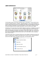
Page 13: ...t row of icons are referred to as Real Time Meters showing the instantaneous values of the parameters The second row of icons are for display of stored data either through trend plots event waveforms and rms plots and reports of either EN50160 data or an annunciator panel of user selectable parameters and their state normal out of limits Also in this second row is the icon for setting up instrumen...

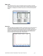
Page 14: ...are formatting a memory card This screen is activated from the PREFERENCES icon on the Home page REAL TIME METER MODES Scope mode Scope mode functions as an oscilloscope displaying real time waveforms of voltage and current for up to eight channels simultaneously with one second update rate The colors of waveform display are user programmable Scope mode also provides a textual display of rms value...

Page 15: ...oth textual and graphical format Harmonics Harmonics display the amplitude and phase of each harmonic to the 63rd harmonic in both graphical and textual format User can select which parameter to show the harmonics for V I W which channel A B C D zoom in a the 5Hz components set options such as showing harmonics and or interharmonics and displaying in Hz or harmonic number scaling to the fundamenta...

Page 16: ...els Functioning as a phase angle meter the unit can display system imbalance conditions and provides such information in textual form also The phase angle display can also verify if monitoring connections have been made correctly Animated phasor demo rotations demonstrating resistive inductive and capacitive loads can be displayed STORED DATA FUNCTIONS and DISPLAYS Trend Users can generate plots f...

Page 17: ...cle s trigger cycle s and post trigger cycles s The event data for all of the captured channels can be displayed in time plots of the rms values or waveforms event details such as trigger conditions characterization of the event according to PQ standards and min max values or the time stamped event list Trend of rms voltage and current Waveforms from transient event capture ...

Page 18: ...Quick Reference Guide for PowerXplorer Power Guide Power Visa pg 18 Detailed information of transient event capture List of events with characteristics ...

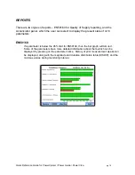
Page 19: ...he present state of 4 16 parameters EN50160 If a parameter is below the 95 limit for EN50160 then the bar graph will turn red Some of the parameters have more detailed information about them which can be displayed by pressing on the parameter name History of prior measurement weeks can be displayed along with the magnitude and duration distribution table DISDIP and the min max values during monito...

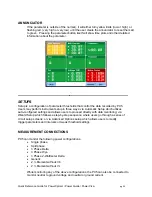
Page 20: ...in three ways via Automatic Setup which utilizes auto configured settings and allows users to proceed directly with data monitoring via Wizard Setup which follows a step by step sequence where users go through a series of circuit setup screens or via Advanced Options setup which allows users to modify trigger parameters and intervals or tweak threshold settings MEASUREMENT CONNECTIONS PX5 can moni...

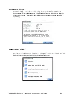
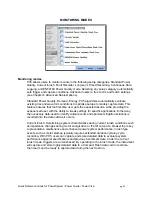
Page 21: ... set the unit automatically Users have the option to view the summary list of parameter settings change probe types if current will be monitored and or proceed directly with data monitoring MONITORING MENU Once the setup either stored automatic or wizard has been completed the user can start monitoring instantly or monitor for a fixed period of time ...

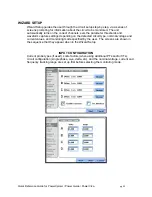
Page 22: ...ter thresholds and waveform capture settings depending on the detected circuit type nominal voltage and current values and monitoring mode specified by the user The screens are shown in the sequence that they appear when in the Wizard Setup INPUT CONFIGURATION Current probe types if used scale factors when using additional PTs and or CTs circuit configuration single phase wye delta etc and the nom...

Page 23: ...Quick Reference Guide for PowerXplorer Power Guide Power Visa pg 23 Includes automatic detection and comparison of wiring versus selected configuration ...

Page 24: ...with the ability to tweak settings for specific applications Either way the necessary data used to identify critical events and optimize mitigation solutions is recorded into the data card as it occurs Current Inrush Determining system characteristics during current inrush conditions such as impedance changes during motor energization or the I2t curve of a breaker trip is key to preventative maint...

Page 25: ...kable portable case option or other available enclosures power quality studies can be carried out in harsh weather environments Continuous Data Logging Demand Energy This logs the rms and power values once per second for totally gapless logging Cyclic triggers are disabled No waveforms are recorded under this monitoring mode EN50160 Power Quality EN50160 monitors and reports Quality of Supply QOS ...

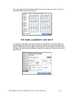
Page 26: ...ference Guide for PowerXplorer Power Guide Power Visa pg 26 The wizard uses interactive graphical images to show the user what the present values are and the effect of the proposed changes as illustrated below ...

Page 27: ...d SITE NAME and MEMORY CARD SETUP The last step in the setup is to select the name for the data file as well as perform any housekeeping functions on the memory card such as format a new card or delete old data by reformatting When multiple monitoring sessions are performed using the same file name the instrument automatically increments and appends a number to the end of the file name ...

Page 28: ...are not connected then you can set your values by pressing the blue bordered box Mode of Operation Select Continue Monitoring Mode Select Standard Power Quality Advanced Options Six Sub categories 1 Transient Leave defaults as long as Nominal Values were correct 2 RMS Variation Leave defaults as long as Nominal Values were correct 3 Waveform Capture Easiest thing to do is set all boxes with a chec...

Page 29: ... FCC Rules These limits are designed to provide reasonable protection against harmful interference when the equipment is operated in a commercial environment This equipment generates uses and can radiate radio frequency energy and if not installed and used in accordance with the instruction manual may cause harmful interference to radio communications Operation of this equipment in a residential a...

Reviews: