background image

Chemdose Manual

7

Pre Operation Checklist

T

REATMENT

A

REA

:

A.  Make sure that the treatment area is vacant.  No humans or pets should be present.

B.  Post all hazard signs before application.

C.  Follow all E.P.A. and W.P.S. guidelines.  Follow all chemical label directions.

C

HEMDOSE

:

A.   Fit the Chemdose with the proper wand for your application situation.   Make sure that
the wand does not leak from any of the fittings.

B.  Dial the dosing knob to the correct output setting.  Dial the interval to the desired length
of time between shots.  Make this time long enough to prevent rushing and inaccurate appli-
cation.

C.  Reset the cycle counter.  Make sure to keep track of the number of shots used on a full
charge to ensure proper dosing.

D.  Test the Chemdose with clear water.  Use each button separately to ensure proper opera-
tion of both.  Make sure that nothing is blocking the output.  Proper flow should be an even,
aerated flow.

E.  Uncoil the hose and make sure that there are no kinks in the hose.

F.    Mix  chemical  solution  according  to  label  guidelines.    (see  "Application  and  Chemical
Mixing" section below)

Application

1. WARNING:   Follow all EPA Guidelines on the handling, application, and re-entry periods
for chemicals.  Only crops listed on the label should be treated.

2. Pre Water plants to be treated.  Most applications of drench products work best when the
plant has been pre-watered.  Ensure that the media is thoroughly saturated.  Some chemi-
cals can be applied to dry soil.  Always defer to the chemical manufacturer recommendations
for application.

3. Determine how you will treat the area and whether or not you will be spot treating individ-
ual plants or treating all the plants in an area.   Choose the correct button for the method
you prefer.

Summary of Contents for CHEMDOSE CD-100

Page 1: ...CHEMDOSE Owners Manual CD 120...

Page 2: ...Mixing 8 Operation 9 Charging 10 MS 20E Sprayer Cart Bottom Draw Instructions 11 MS 20E Sprayer Cart Tank Assembly Diagram Parts List 12 Chemdose Assembly Diagram Parts List 13 Chemdose Pump Assembly...

Page 3: ...machine without proper ventilation Mix only the amount of chemical solu tion which will be used NEVER Keep store or hold over unused chemical solu tion Follow all E P A guidelines and chemi cal label...

Page 4: ...changing the preci sion of each dose A cycle counter is located on the control face of the Chemdose to help with counting The Chemdose cart and tank are designed to fit down standard green house aisle...

Page 5: ...ach button separately to ensure proper opera tion of both Make sure that nothing is blocking the output Proper flow should be an even aerated flow E Uncoil the hose and make sure that there are no kin...

Page 6: ...ount of product per 100 gallons 1 2 3 4 5 6 7 8 9 10 11 12 amount to mix in 20 gallons 0 2 0 4 0 6 0 8 1 0 1 2 1 4 1 6 1 8 2 0 2 2 2 4 amount of product per 100 gallons 13 14 15 16 17 18 19 20 21 22 2...

Page 7: ...osing 5 Keep track of the number of shots per full charge After 16 000 shots the volume will decrease from the pump even though the machine will appear to dose correctly 6 After application thoroughly...

Page 8: ...eptacle on the Chemdose 3 Switch the three position switch to charge The Fast Charge light should come on indicating charge If the Fault light comes on see trouble shooting on page 16 4 Allow to charg...

Page 9: ...ter street elbow and hose barb fitting together Then screw the assembly into the tank 4 With the tank in the cart with the outlet to the rear and the Chemdose in place measure the red suction hose fro...

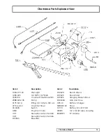
Page 10: ...2 DII096 Handle Assembly 1 3 DIII20A MSO Pump Bracket 1 4 DIII21 Side Leg 2 5 DIII59 Chemdose Bracket 1 6 DI0563 Chemdose Box 1 7 1899041 6 Caster 2 8 SNI0275 OP 5 8 10 X 2 Wheel 2 9 SP0020 LC 20 Gal...

Page 11: ...1 One Shot Timer 90 0003 Switch A3M Plug 3 pin male C3F Receptacle 3 pin female C4F Receptacle 4 pin female D10563 Steel Box D10624 Bench Wand D10625 Floor Wand D10626 Hanging Basket Wand D10633A Grip...

Page 12: ...94 236 11 94 231 05 94 230 05 94 237 05 94 231 30 94 232 05 94 238 03 11 111 00 Complete Pump Head Upper Housing Switch assembly Switch kit Check Valve Kit Upper Housing Kit Valve Kit Diaphragm Drive...

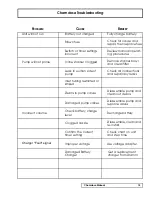
Page 13: ...bris in pump valves Disassemble pump and clean out debris Check all connections and repair any leaks Damaged pump valves Disassemble pump and replace valves Clogged nozzle Disassemble clean and re ins...

Reviews: