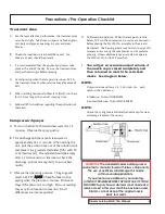
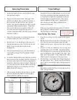
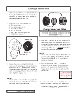
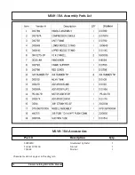
background image

21

Dramm Autofog MLVH-10A Manual

1.     The spray pattern exits the nozzle in short bursts – it

should exit as a steady stream.

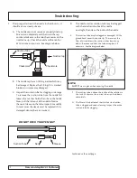
       A.    The nozzle cap is not secure or properly lined up.

               Screw it on completely and then turn the cap
               counter clockwise so the two check marks on the
               nozzle line up.  Check the nozzle calibration for
               45cc/minute output rate.  See diagram below.

       B.    The nozzle cap has an O-Ring inside which may

               be damaged.  Replace the O-Ring if it is cracked,
               broken or in some way damaged.

       C.    Inspect the suction tube for clogging or damage.

               To remove the suction tube from the nozzle first
               loosen the nut that holds the tube to the nozzle.
               Now, pull the tube out of the nozzle. Notice 
               the metal sleeve on the tube, inspect it carefully.
               In most cases the sleeve must be replaced if it is
               damaged, dented, bent or cracked.

DO NOT OVER TIGHTEN NUT

D.      The nozzle and/or solution tank may be clogged

       with chemical residue. Soak the nozzle
       overnight, then clean the inside of the nozzle.

E.        The suction tube may be clogged or damaged.  With a

        gloved hand, cover the nozzle tip.  This reverses the
        flow of air and blows the suction tube clean of any
        debris.  Remove and clean the tube or replace it if
        necessary.  See the diagram below.

F.     The suction tube is above the surface of the solution in

        the tank.  Make sure the suction tube is pushed down
        completely.

G.    The filter at the bottom of the stainless steel suction

        tube is clogged and needs cleaning.  Inspect the entire
        suction tube for clogging.

Continued on the next page...

Suction Tube

Nut

Sleeve

Troubleshooting

NOTE:


ALWAYS 

wear a glove when covering the nozzle.

Nozzle Cap

Checkmark

Checkmark

Suction Tube

Summary of Contents for Autofog MLVH-10A

Page 1: ...AUTOFOG MLVH 10A Owners Manual...

Page 2: ...ion Checklist 8 Chemical Mixture and Application 9 Low Rate Calculations 10 High Rate Calculations 11 Spraying Procedure Timer Settings 12 Cleaning Maintenance 13 Assembly Diagram 14 Assembly Parts Li...

Page 3: ...l Before Re Entry Air Must Be Changed By Venting Follow all EPA Guidelines for re entry periods Do Not Use This Machine In An Enclosure Where Vapors Can Enter Any Type Of Air Vents Care should be take...

Page 4: ...k where the suction tube should rest Place the agitator back into the solution tank and secure with the turn tabs 6 On the control panel insert air hose into the press fit connection marked AIR TO NOZ...

Page 5: ...which will range in size from 5 to 10 microns in diameter Air enters the nozzle from the oil less compressor and then exits the nozzle at super sonic speeds This movement of air creates a venturi tha...

Page 6: ...aying when the temperature is over 85 F in the treatment area or when relative humidity exceeds 85 E When utilizing horizontal airflow fans HAF run them for 1 2 hour longer than actual spraying time F...

Page 7: ...ne to avoid spilling the chemical solution 6 Connect the MLVH 10A to a 120V 60HZ power source and set the timer by rotating past and then returned to the desired spraying time The spraying process beg...

Page 8: ...of 15 to 1 for Wettable Powders and Flowables A ratio of 10 to 1 for Emulsifiable Concentrates Note New chemicals or chemicals which have been re labeled may recommend how many ounces should be applie...

Page 9: ...liters Make Your HIGH RATE Calculations Below CHEMICAL LABELED RATE PER 100 GALLONS RATE FOR 10 000 SQUARE FEET RATE FOR 5 000 SQUARE FEET MINIMUM AMOUNT OF WATER FOR 5 000 SQ FT 16 oz X 35 6 4 oz 12...

Page 10: ...Be sure that the solution is free of clumps of chemical that may clog the nozzle Use a whisk or blender to make a smooth paste of wettable powder solutions Check that the suction tube screen is in pl...

Page 11: ...mpressor housing on top of the compressor Brush any excess debris off the filter and then rinse with warm water Use a mild detergent if necessary ALWAYS let the filter air dry completely before reinst...

Page 12: ...Dramm Autofog MLVH 10A Manual 14 MLVH 10A Assembly Diagram...

Page 13: ...m Autofog MLVH 10A Manual MLVH 10A Assembly Parts List MLVH 10A Accessories Part Description Qty 500926M Graduated Cylindar 1 Funnel LVM100 Funnel 1 153582 Strainer 1 these items do not appear in the...

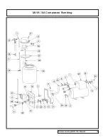
Page 14: ...Dramm Autofog MLVH 10A Manual 16 MLVH 10A Compressor Plumbing...

Page 15: ...MLVH 10A Compressor Plumbing Parts List 17 Dramm Autofog MLVH 10A Manual...

Page 16: ...MLVH 10A Compressor Diagram Dramm Autofog MLVH 10A Manual 18...

Page 17: ...MLVH 10A Compressor Parts List 19 Dramm Autofog MLVH 10A Manual...

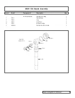
Page 18: ...sembly Item Part Component Description Qty D7513670000A Nozzle Assembly 1 1 7010 Nozzle Base 1 2 7020 Cap 1 3 7030 Lock Nut 1 5 7100 Extension Pipe 1 7 D10151 Stainless Suction Tube 1 7460 Fits Inside...

Page 19: ...it carefully In most cases the sleeve must be replaced if it is damaged dented bent or cracked DO NOT OVER TIGHTEN NUT D The nozzle and or solution tank may be clogged with chemical residue Soak the n...

Page 20: ...ctive or broken Replace it 4 Pressure gauge reads too high A Piping is clogged Check the entire piping for obstructions and replace any defective or clogged sections B A clogged nozzle or nozzle cap w...

Reviews: