POWER
ERROR
VMM806AG
CATV
+100
VIDEO
A / V
RF
AUDIO
CATV
BC
TV
2
5
F1
F2
F3
F4
F5
F6
F7
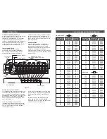
REAR PANEL CONNECTIONS / INTERNAL JUMPERS 3
2
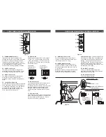
FRONT PANEL CONTROLS and INDICATORS
Figure 1
R1
R2
R3
R4
AUDIO - FLAT
AUDIO PRE-EMPHASIS
(factory setting)
Figure 2
AUDIO INPUT -
Baseband audio,
(factory setting)
AUDIO INPUT -
4.5 MHz modulated
carrier
A.
B.
C.
A.
B.
C.
B.
C.
PRE-EMPHASIS / FLAT:
AUDIO INPUT CONNECTOR:
Figure 3
R1 - VIDEO INPUT Connector
This is the baseband video input to the IF
circuits. This input accepts baseband input
levels from 0.6 Vp-p to 1.5 Vp-p.
R2 - AUDIO INPUT Connector
This is an unbalanced audio input to the IF
circuits. This “RCA” (phono) connector input
accepts baseband audio from 100 mVrms to
3 Vrms levels.
NOTE: An internally selected test point jumper
defeats the audio pre-emphasis for stereo
capability. See the illustration on this page.
4.5 MHz Audio Input: This AUDIO INPUT can
also accept a 4.5 MHz audio modulated carrier
by reconfiguring two specified internal jumper
settings. Required 4.5 MHz input level is
+40 dBmV ±2 dB. Some stereo generators or
satellite receivers provide audio output in a
4.5 MHz audio modulated carrier format. See
the illustration on this page.
R3 - DC INPUT Connector
This 3-pin connector (Male) accepts the
appropriate mating DC power cable. Observe
proper orientation and wiring.
R4 - RF OUTPUT Connector
This is the modulator output.
F1 - POWER/ERROR Indicator
Lights when the unit is connected to the
required source of DC power via the rear panel
DC INPUT connector. A flashing condition
indicates an invalid channel setting or other
conditions that would cause the unit to operate
on an invalid channel. The RF output is
switched off for flashing (ERROR) conditions.
F2 - AUDIO Level Control
The setting of this screwdriver adjustment
determines the aural carrier deviation. Clock-
wise rotation increases the carrier deviation.
F3 - VIDEO Level Control
The setting of this screwdriver adjustment
determines the video modulation level.
Clockwise rotation increases the modulation
depth.
F4 - Channel Number Switch
Sets the desired operating channel for standard
CATV channels 02 through 125 or Broadcast
TV channels 02 through 69. See also Item F5
which sets the type of channel (CATV or
Broadcast TV) and sets the leading “1” for
CATV channels 100 through 125.
F5 - Mode Switch
Sets the type of channel, CATV or Broadcast
TV (“BC TV”). The first position of the switch
(“+100”) sets a leading “1” for CATV channels
100 through 125. See also Item F4 for setting
the channel number.
For example:
For example:
Setting for CATV
Setting for CATV
channel "125"-
channel "25"-
CATV
+100
CATV
BC
TV
2
5
CATV
+100
CATV
BC
TV
2
5
F6 - A/V Ratio Control
This screwdriver adjustment varies the level of
the aural carrier over a range from 11 to
18 dB below the visual carrier. The aural carrier
should be adjusted to approximately 15 dB
below the visual carrier (normal operation).
Clockwise rotation increases the aural carrier
level.
F7 - RF Output Level
This screwdriver adjustment permits decreasing
the RF output level a minimum of 15 dB as the
control is rotated counterclockwise. Set the
control for a +45 dBmV output level .


