background image

7


Adjustments

Adjustments

VIDEO LEVEL:  With the intended signal source connected and a representa ve video program present turn the Video 

Level  Adjust  control  clockwise  un   the  Video  Overmodula

  light  just 

ashes,  then  back  o

  slightly. 

Alterna vely, while watching the picture on a good TV monitor, adjust the control to the highest (clockwise) 
level that does NOT cause the highlights (white por

 of the picture) to become “washed out”.

AUDIO LEVEL:  Turn the Audio Level Adjust control clockwise un  the Audio Overmodula

 light just 

ashes slightly on 

the loudest peaks of the audio program material.

OUTPUT LEVEL:  The Output Level is adjusted by pressing the UP or DN bu on when in the Output Level display mode. 

The LED display will blink indica g a transi on state. The output level is not changed un  the ENTER 
bu on is pressed. If the ENTER bu on is not pressed, the display will return to its res g state a er 30 
seconds. Pressing and holding the UP or DN bu on will allow for faster scrolling. The Level increments in 
0.2 dB steps. Output level accuracy is typ/- 1 dB of display, +/- 2 dB worst case. 

A/V CARRIER RATIO:  To adjust the aural-to-visual carrier ra o, tune the RF indicator device to the aural carrier frequency 

and adjust the Aural Carrier control to obtain the desired aural carrier level. Recommended ra  is 
-15 dB.

EAS/ALT IF:

AUTOMATIC:  Connect a jumper to the terminal strip auto posi

 EAS will switch on when

 a +30 dBmV EAS IF signal is detected.

MANUAL:  EAS is ac ve with a ground connec

 on the manual posi

 of the terminal strip.

Summary of Contents for VM2050

Page 1: ...ed trademark of the R L Drake Holdings LLC Printed in China VM2050 VM2551 Commercial Video Modulator For use in NTSC systems Rev 20151111 1002412A 1002423A VM SERIES VIDEO MODULATOR Copyright 2015 R L Drake Holdings LLC P N 651232400B ...

Page 2: ... damage to the product due to lightning and power line surges 16 Power Lines An outside antenna system should not be located in the vicinity of overhead power lines other electric light or power circuits where it can fall into such power lines or circuits 17 Overloading Do not overload wall outlets extension cords or integral conve nience receptacles as this can result in a risk of fire or electri...

Page 3: ...cuits électriques Entrer en contact avec de tels circuits ou lignes électriques pourrait être fatal 17 Surcharge Ne pas surcharger les prises de courant murales les rallonges élec triques ou les prises de courant intégrées Un risque d incendie ou de choc électrique pourrait résulter d une telle surcharge 18 Insertion d objet ou de liquide Ne jamais insérer d objet par les ouvertures de cet apparei...

Page 4: ...the rear of the unit In the manual mode the EAS ALT IF feature is activated by a contact closure switch which completes a ground connection In the automatic mode two positions on the terminal strip are jumpered together enabling an automatic detection circuit in the unit When an EAS ALT IF signal is routed to the EAS ALT port the unit automatically switches to that alternate signal DESCRIPTION SPE...

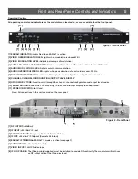
Page 5: ...tput level and modes 8 CHANNEL CHANNEL CONFIGURATION OUTPUT LEVEL DISPLAY 9 UP DOWN BUTTONS Used to scroll through the channel channel configuration and output level modes 10 ENTER BUTTON Evokes the current settings in the channel output display when depressed 11 STEREO INDICATOR Not Used Note All connections to the unit are made at the rear panel 1 RF OUTPUT 60dBmV 2 IF INPUT 35 dBmV IF Input 3 E...

Page 6: ... on when in the Channel Configura display mode The LED display will blink indica g a transi state The channel configura is not changed un the ENTER bu on is pressed If the ENTER bu on is not pressed the display will return to res g state a er 30 seconds If the mode is to be changed and it is not a valid mode for the exis g channel when the ENTER bu on is pressed the new mode will be selected and the...

Page 7: ...when in the Output Level display mode The LED display will blink indica g a transi on state The output level is not changed un the ENTER bu on is pressed If the ENTER bu on is not pressed the display will return to its res g state a er 30 seconds Pressing and holding the UP or DN bu on will allow for faster scrolling The Level increments in 0 2 dB steps Output level accuracy is typically 1 dB of d...

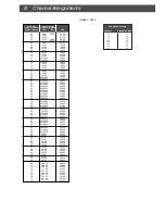
Page 8: ...3 24 25 26 27 28 29 30 31 32 33 34 35 36 37 38 39 40 41 42 43 44 45 46 47 48 49 50 51 52 53 54 55 56 57 58 59 60 61 62 63 64 65 66 67 68 Visual Carrier Frequency MHz STD IRC N A 55 25 61 25 67 25 77 25 83 25 175 25 181 25 187 25 193 25 199 25 205 25 211 25 121 2625 127 2625 133 2625 139 25 145 25 151 25 157 25 163 25 169 25 217 25 223 2625 229 2625 235 2625 241 2625 247 2625 253 2625 259 2625 265 ...

Page 9: ...ADCAST CHANNELS UHF BROADCAST CHANNELS UHF BROADCAST CHANNELS UHF BROADCAST CHANNELS UHF BROADCAST CHANNELS Channel Number 55 25 61 25 67 25 77 25 83 25 175 25 181 25 187 25 193 25 199 25 205 25 211 25 2 3 4 5 6 7 8 9 10 11 12 13 Visual Carrier Frequency MHz VHF BROADCAST CHANNELS VHF BROADCAST CHANNELS VHF BROADCAST CHANNELS VHF BROADCAST CHANNELS VHF BROADCAST CHANNELS Channel Number TABLE 2 BRO...

Page 10: ...o you 6 Securely pack the product in its original undamaged box returning the product without its original packaging in good new condition may cause the incursion of additional fees Pack this box within another shipping container or box Mark the shipping box or container with your RMA Number Place the RMA Number near the return address in large bold print approx 2 in height Ship your CREDIT RETURN...

Page 11: ... writing between the parties for a period of ninety 90 days from the date of original purchase Notwithstanding the foregoing in some cases the warranty on certain proprietary sub assembly modules manufactured by third party vendors and contained in Seller products third party software installed in certain of Seller s products and on certain private label products manufactured by third parties for ...

Page 12: ...R L Drake Holdings LLC 710 Pleasant Valley Drive Springboro Ohio 45066 Customer Service and Parts Telephone 1 937 746 6990 Telefax 1 937 806 1510 World Wide Web Site http www rldrake com ...

Reviews: