8 Setup and Programming
Programming and viewing of the various setup and
operating parameters is accomplished using the front panel
back lit, two line, sixteen character wide LCD along with the
4 arrow buttons and the ENTER button. The name of the
parameter is on the top line of the display and the setting
value is on the bottom line.
To observe a certain parameter setting without intending to
change its value, just use the left and right arrow buttons to
navigate through the menus shown in the list. The current
setting for each parameter is shown on the bottom line of
the display. Note that depending upon certain settings,
some screens are not needed and will be skipped.
To make a change in the displayed parameter and its
setting and if this is the initial setup, you will want to enter
the ‘adjust’ mode. To do this, press the ENTER button that
is located in the center of the four arrow buttons and hold in
for several seconds until the display begins to flash. After
you are in the adjust mode (bottom line of screen flashing)
use the left and right arrows to navigate among screens
and use the up and down arrows to change the parameter
setting. When ENTER is pressed, the new settings will be
loaded and stored and the unit will exit the ‘adjust’ mode.
You may wish to not press ENTER until you have gone
through all screens and settings and then press ENTER to
save and load all changes in one step OR you can store
just one or several parameters at a time and reenter adjust
mode to set the next. Either method is acceptable.
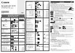
Menu Item
Parameter Setting Choices
Top display line.
Second display line.
Use left/right arrows Must be in adjust mode to change
to navigate.
using up/down arrows.
UNIT ID:
# (0 thru 63)
RS232 BAUDRATE: 2400
4800
9600
19,200
MPEG PROGRAMS: DEFAULT
SELECT PROGRAMS
QAM MODE:
QAM-16A
QAM-32A
QAM-64A
QAM-128A
QAM-256A
QAM-512A
QAM-1024A
QAM-64B
QAM-256B
QAM-1024B
GRAY ENCODING:
(This menu item only appears if
QAM modes QAM-16A thru QAM-
1024A are selected.)
DVB
DAVIC
QAM SYMRATE:
PRESET
MANUAL
QAM SYMRATE:
x.xxxx MSym/Sec
(only in manual)
OUTPUT FORMAT:
NORMAL
CW
STANDBY
PRBS 15
PRBS 15M
PRBS 24
PRBS 23M
OUTPUT CHANMAP:
BROADCAST
CATV
IRC
HRC
OUTPUT CHANNEL:
2 thru 69 (broadcast)
2 thru 158 (CATV)
1 thru 158 (IRC & HRC)
RF LEVEL:
xx.x dBmV (+30 to +42 dBmV)
UNIT ID: Select the desired unit identification number
when connecting the 'RS232 IN' connector to a PC or
modem for remote control using 'Drake Remote Control
Software'. Numbers 1 thru 63 may be used. If zero (0) is
selected, the PC will ignore the unit.
RS232 BAUD RATE: This setting determines the baud
rate at which the MQM6000L communicates with the
remote PC. Settings available are 2400, 4800, 9600 and
19,200. All units 'daisy chained' to the remote PC or
modem must be set to the same baud rate.
MPEG PROGRAMS: This menu provides selections to
determine which programs are multiplexed to form the new
multiprogram transport stream output that will be supplied
to the QAM modulator section.
Choose the DEFAULT setting to multiplex the lowest
numbered (or only) MPEG program from each of the six
ASI inputs.
Choose the SELECT PROGRAMS setting to allow the
operator to pick which program (or no program) from each
of the six ASI inputs is to be included in the output multi-
plex. Only one program from each of the six inputs can be
selected. This selection must be made using a PC
connected to the RS232 IN port and running the 'Drake
Digital Headend Remote Control Software' program.
It is the operator's responsibility to be sure that the total
data rate of these programs does not exceed the maximum
data rate for the output QAM mode that will be used. If the
total input rate is too large, some programs will have to be
dropped from the multiplex.