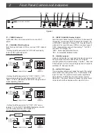
2 Front Panel Controls and Indicators
CATV
HCP1550 CHANNEL PROCESSOR
POWER
CATV
OFF AIR
IRC
HRC
STD
INPUT
CHANNEL
OUTPUT
CHANNEL
x 6.25 kHz
SIGNAL
OUTPUT ENABLED
100
+
RF INPUT
A / V RATIO
LEVEL
RF OUTPUT
OFFSET
7
8
0
4
4
CHANNEL PLAN
--
+
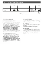
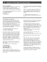
F1 – POWER Indicator
Lights when the unit is connected to a source of AC
power.
F2 – CHANNEL PLAN Switches
Sets the type of channel, Off-Air or various CATV channel
plans.
- Setting the left-hand switch for “OFF AIR” electrically
locks out the right-hand switch.
OFF-AIR CHANNEL 25:
CATV
CATV
OFF AIR
IRC
HRC
STD
INPUT
CHANNEL
100
+
RF INPUT
2
5
CHANNEL PLAN
- Setting the left-hand switch for “CATV” ("CATV + 100")
also requires setting the right-hand switch for “IRC”,
“HRC”, or “STD” (standard) as desired for the given input
signal operating channel.
STANDARD CATV CHANNEL 25:
CATV
CATV
OFF AIR
IRC
HRC
STD
INPUT
CHANNEL
100
+
RF INPUT
2
5
CHANNEL PLAN
- Setting the left-hand switch for “CATV +100” sets a
leading ”1” to the INPUT CHANNEL thumbwheel switch
for CATV channels from 100 through 125.
STANDARD CATV CHANNEL 125:
CATV
CATV
OFF AIR
IRC
HRC
STD
INPUT
CHANNEL
100
+
RF INPUT
2
5
CHANNEL PLAN
Figure 1
F1 F2 F3 F4 F5 F6 F7 F8 F9
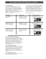
F3 – INPUT CHANNEL Number Switch
Sets the input channel number for Off-Air TV channels 02
through 69, for standard CATV channels 02 through 125,
or IRC,HRC* channels 01 through 125. See also Item F2
which sets the type of channel (Off-Air or various types of
CATV channel plans) and sets the leading “1” for CATV
channels 100 through 125.
*HRC - Harmonically Related Carrier.
*IRC - Incrementally Related Carrier.
F4 – SIGNAL Indicator
Lights to indicate that an input signal is being received as
set by the input channel switches and is of a signal
strength greater than approximately –10 dBmV. Note that
if this indicator is off (no received signal), the RF output is
switched off. See also Item F8.
F5 – A/V RATIO Control
This screwdriver adjustment varies the level of the output
aural carrier over a range from 0 to –10 dB relative to the
input A/V ratio. The aural carrier should be adjusted to
approximately 15 dB below the visual carrier (normal
operation). Clockwise rotation increases the output aural
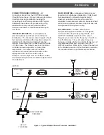
carrier level and thus decreases the output A/V ratio.


