Table of Contents / Description / Specifications 1
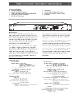
CATV
HCP1550 CHANNEL PROCESSOR
POWER
CATV
OFF AIR
IRC
HRC
STD
INPUT
CHANNEL
OUTPUT
CHANNEL
x 6.25 kHz
SIGNAL
OUTPUT ENABLED
100
+
RF INPUT
A / V RATIO
LEVEL
RF OUTPUT
OFFSET
7
8
0
4
4
CHANNEL PLAN
--
+
DESCRIPTION
The R. L. Drake HCP1550 is a high quality, frequency
agile channel processor capable of converting any VHF,
UHF, or CATV input signal to any standard output channel
between 54 and 550 MHz. Input and output frequency,
including output frequency offset are easily set with front
panel pushwheel switches. A/V ratio and output level
controls are also provided along with IF loop-thru
connections to offer exceptional flexibility.
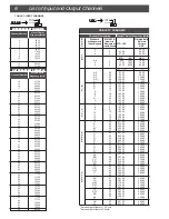
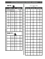
The synthesized input tuning permits reception of Off-Air
TV channels 2 through 69, standard CATV channels 2
through 125, and IRC, HRC channels 1 through 125. A
front panel signal indicator lights for input signal strengths
greater than a threshold value. The synthesized RF
output can be set for any CATV channel 2 through 78 and
95 through 99. The output frequency offset can be set for
none or in increments of 6.25 kHz plus or minus up to
56.25 kHz maximum offset.
Knowledge of the input signal frequency and the desired
output frequency is important prior to setting any offset.
RF output level is front panel adjustable to +60 dBmV
maximum.
IF loop-thru capability in the HCP1550 supplies a padded
IF output prior to channel conversion. This feature
provides the capability to replace the standard internally
generated IF output with an alternate source of composite
IF, or allows the insertion of IF scrambling equipment.
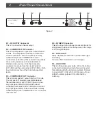
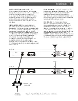
Coaxial connectors are provided for the RF Input, the IF
Loop-out and Loop-in, and the RF Output. All of the
mentioned features, combined with a carefully designed
low intermodulation output stage, provide reliable
operation in a densely crowded SMATV or cable
environment.
TABLE OF CONTENTS
ii
Caution Statements
ii
Important Safety Instructions
1
Table of Contents / Description / Specifications
2
Front Panel Controls / Indicators
4
Rear Panel Connections
5
Installation
6
List of Input and Output Channels
8
Service / If You Need To Call For Help
9
Warranty
X
54 to 806 MHz:
Off-Air TV channels 2 to 69;
Standard CATV channels 2 to 125;
IRC and HRC channels 1 to 125.
75 Ohms.
-10 dBmV to + 35 dBmV.
Greater than 60 dB.
VHF, 8 dB. UHF, 10 dB.
VHF, 65 dB. UHF, 50 dB.
+28 dBmV ±2 dB.
-60 dBc minimum.
+28 dBmV nominal,
+30 dBmV maximum.
75 Ohms, greater than 15 dB return loss.
Greater than 60 dB.
SPECIFICATIONS
INPUT SECTION
Frequency Range:
Input Impedance:
RF Input Level:
Adjacent Channel
Rejection:
Noise Figure:
Tuner Image Rejection:
COMPOSITE IF LOOP
Output Level
(V carrier):
Spurious Outputs:
Input Level (V carrier):
IF Input/Output
Impedance:
Isolation:
X
82 channels, 54 to 550 MHz;
Channels 2 to 78 and 95 o 99.
+60 dBmV (typically adjustable from
+50 to +60 dBmV).
20 Hz to 4.2 MHz, ±3 dB.
±50 nSec.
±5 PPM of frequency difference
between input and output signals.
Selectable - None or increments of
6.25 kHz plus or minus up to
56.25 kHz maximum offset.
Typically 0 to -10 dB relative to input
A/V ratio.
-58 dBc minimum, -60 dBc typical
(measured at an input level of between
0 to +20 dBmV).
-75 dBc typical,
(4 MHz noise bandwidth @ ±12 MHz).
115 VAC (±10%), 60 Hz, 30 Watts.
0
0
C to + 50
0
C, ambient.
19" W x 1.75" H x 8.75" D.
7.0 lbs.
X
OUTPUT SECTION
Frequency Range:
Output Level:
Video Frequency
Response:
L-C Delay:
Frequency Stability:
FCC Offset:
A/V Ratio Adjustment:
Spurious Outputs:
Broadband Noise:
GENERAL
AC Power Input:
Operating Temperature:
Dimensions:
Weight:


