background image

33

32

TiTre

TiTre

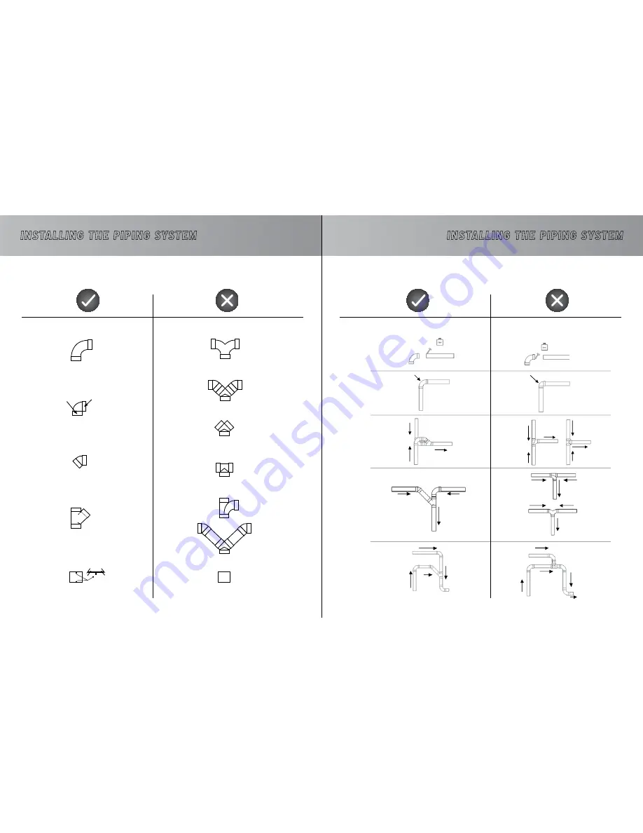
INSTALLING THE PIPING SySTEM 

eXAmpLes oF proper AND improper iNstALLAtioNs

Joint with inside stoppers

Thick wall

Thin  wall  

For wall plates only

Smooth joint without inside stoppers

INSTALLING THE PIPING SySTEM

eXAmpLes oF proper AND improper iNstALLAtioNs

Summary of Contents for DF1A150

Page 1: ...OWNER S MANUAL Automatik series For an online version of this manual readable with a smart phone ...

Page 2: ...gers all body parts and loose clothing away from any openings Never plug in a unit designed to operate with a current of 120V in a 230V outlet and vice versa Ifthepowercordisdamaged itmustbereplacedbyaspecialcordavailablefromtheauthorizedlocaldealer distributor Do not use extension cords or outlets with inadequate current carry capacity Never operate this vacuum if it has a damaged cord or plug if...

Page 3: ... DF2A32 15 DVDC40 DFDC40 SEries configuration 16 DVDC40 DFDC40 parallel configuration 17 How the Membrane Works Why Change this Parameter Setting the Evacuation Timeframe 18 Installing the Unit First Things First 19 20 Step Sequence 21 27 Installing the Piping System General Information 28 FROM DRY TO WET 29 Different Installation Possibilities Residential and Commercial Installation 30 31 Example...

Page 4: ... 1 Unit is off Step 2 Start up The dirt begins to be vacuumed and water flows in The water comes into contact with the electrodes The rubber hand opens The rubber hand is closed Step 3 Water flows in reaching the level of the electrodes approx 10 minutes Step 4 The wastewater is evacuated to the sewer approx 20 seconds To see a video of the sequence go tohttp youtu be KdPL3ysamgY OPERATION SeQUENC...

Page 5: ... 2 4 2 1 2 in series 1 2 in series 1 2 2 4 2 Amps Amps Amps Amps 14 18 18 2 x 18 2 x 13 13 18 7 5 11 8 10 8 10 8 2 x 10 8 2 x 7 5 CapacitY gal l CapacitY gal l 4 gal 18 L 6 gal 29 L 6 gal 29 L 6 gal 29 L 6 gal 29 L 4 gal 18 L 6 gal 29 L 6 gal 29 L 6 gal 29 L 6 gal 29 L Dimensions in cm Dimensions in cm FOR MODELS FOR MODELS Dimensions in cm Dimensions in cm 12 dia x37 30cmdia x93cm 15 dia x49 38cm...

Page 6: ...ER TANK ADVANTAGES Facilitates maintenance To remove oversized materials or an accumulation of hair paper etc Strongly suggested when the unit is used by many people commercial applications The lower tank option is always recommended when enough space is available BOOSTER HEAD OPTION Standard head Booster head booster head advantages For additional power to your unit When space is limited the boos...

Page 7: ...pply 2 motor unit Porthole O ring Porthole window Outdoor vent Dust entry Rubber hand Power cord Water discharge Dia 2in 5cm uNIT DESCRIPTION DV2A310 DF2A310 Vacuum pipe Audioprotek muffler 24V plug Cold water supply One motor unit Porthole O ring Porthole window Outdoor vent Dust entry Water discharge Dia 2in 5cm Power cord ...

Page 8: ...window Outdoor vent Outdoor vent Dust entry Rubber hand Power cord Audioprotek muffler Audioprotek muffler Power cord 24V plug Water discharge Dia 3in 7 6cm uNIT DESCRIPTION DV2A32 DF2A32 Vacuum pipe Audioprotek muffler 24V plug Cold water supply 2 motor unit Porthole O ring Porthole window Outdoor vent Dust entry Rubber hand Power cord Audioprotek muffler Water discharge Dia 3in 7 6cm ...

Page 9: ...mended for optimum air flow Suction Power 120 H2O 2832 mmH2O Air Flow 200 CFM 340 m3 h Water discharge Dia 3in 7 6cm uNIT DESCRIPTION DVDC40 DFDC40 parallel configuration for optimum air flow Vacuum pipe Audioprotek muffler 24V plug One motor booster head 24V plug Cold water supply One motor unit Porthole O ring Porthole window Outdoor vent Dust entry Power cord Audioprotek muffler Power cord The ...

Page 10: ...ting the wastewater Evacuation Time Minimum 5 seconds Maximum 35 seconds WHY CHANGE THIS PARAMETER With a lower tank model the unit can reactivate as soon as there is no wastewater left to flow through the rubber hand in other words when all the wastewater is in the lower tank If the unit s drain is located very close to the pipe leading to the sewer and that there is less restriction to the amoun...

Page 11: ... cm INSTALLING THE UNIT sTEP SEQUENCE Where will you install the unit We recommend installing the system on the lowest level of the building to avoid having to work against gravity The basement is generally the most ideal location near the building s main drainpipe A cold water pipe must also be available and connected to the unit Vents are necessary if the unit is further then 6 2m away from the ...

Page 12: ...talled according to the available space without compromising the height of the head in relation to the unit However we recommend that you keep the number of joints elbows to a minimum to optimize air circulation and performance POSITIONING A BOOSTER HEAD POSITIONING THE LOWER TANK Not recommended A backflow preventer may be required in some municipalities It is installed at the water input of the ...

Page 13: ... do not glue An air outlet leading outside the building is mandatory for all Automatik systems If your model includes 2 motors the air outlet is on top of the unit If it only includes 1 motor the air outlet is on the side of the unit Air Outlet INSTALLING THE UNIT sTEP SEQUENCE Some units are equipped with two water injectors In this case it is important that they be positioned facing each other s...

Page 14: ...models equipped with only one motor include only one muffler centered on the top of the unit INSTALLING THE UNIT sTEP SEQUENCE Steel Muffler STEEL MUFFLER MODELS DV1A150 AND DF1A150 Some units are equipped with a red steel muffler to absorb the noise produced by more powerful systems Contrary to plastic mufflers this steel muffler must be installed on the wall Installation instructions are provide...

Page 15: ...rts that we recommend for the optimum performance of your central vacuum system GENERAL INFORMATION An air outlet leading to outside must always be installed on your unit Make sure that the evacuated air does not lead under a carport If your unit includes two motors it is important to use metal piping and couplings for the air outlet To determine where to locate the wall inlets use the length of t...

Page 16: ... under the floor On an intermediary floor Always have a slight inclina tion of the piping towards the unit Inclination INSTALLING THE PIPING SYSTEM DIAGRAM OF A COMMERCIAL INSTALLATION In the basement connected under a pipeline under the floor Back to back Always have a slight inclination of the piping towards the unit Under the floor Through the ceiling Installation example in series Inclination ...

Page 17: ...ING SYSTEM EXAMPLES OF PROPER AND IMPROPER INSTALLATIONS Joint with inside stoppers Thick wall Thin wall For wall plates only Smooth joint without inside stoppers INSTALLING THE PIPING SYSTEM EXAMPLES OF PROPER AND IMPROPER INSTALLATIONS ...

Page 18: ...led diagram of the appropriate connections for your model Install the 24 volt wires from the network each wall inlet to the unit If your unit includes one or several booster heads 24 volt wires must be connected to each head as illustrated on the following page refer to the diagram of your particular model Connect the unit to the electrical outlet with the power supply cord The vacuum cleaner is n...

Page 19: ...ides a path of least resistance for electric current to reduce the risk of electric shock This appliance is equipped with a cord having an equipment grounding conductor and grounding plug The plug must be inserted into an appropriate outlet that is properly installed and grounded in accordance with all local codes and ordinances WARNING Improper connection of the equipment grounding conductor can ...

Page 20: ...r brushes after 500 hours of use to check how worn they are and replace them if need be On average this inspection should occur For residential applications once every 3 to 5 years For commercial applications once or twice a year When the time comes contact your retailer or distributor for this maintenance procedure WEEE GUIDELINES MAINTENANCE PROCEDURES Use a scouring sponge to especially clean t...

Page 21: ...120 VOLTS Residential DV1A150 DV2A310 commercial DV2A31 DV2A32 DVDC40 Titre THE UNIT WON T START UP Solution 1 Check the circuit breaker in your electrical panel 2 Check the unit s circuit fuse breaker 3 Check the 24 volt circuit as follows Try to establish electrical contact in a wall inlet with a metal object for example a coin If the unit starts up the suction hose is defective If the unit does...

Page 22: ...OTOR L 2 MOTEUR MOTOR N 1 MOTEUR MOTOR N NEUTRE ÉLECTROVANNE SOLENOID VALVE NEUTRAL NEUTRE COMPTEUR HORRAIRE NEUTRAL TIMER NEUTRE TRANSFO NEUTRAL TRANSFO NEUTRE BLEU BLUE NEUTRAL ALIMENTATION 1 SUPPLY ALIMENTION FUSIBLE 230 VOLTS FUSE LINE PONT DE J30 À J10 SEULEMENT POUR COMMERCIAL JUMPER J30 TO J10 ONLY FOR COMMERCIAL ALIMENTATION TRANSFO TRANSFO LINE ALIMENTATION COMPTEUR HORAIRE TIMER LINE ALI...

Page 23: ...PRINTED IN CANADA 06 15 ...

Reviews: