


contact us at
www.DRpower.com
29
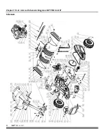
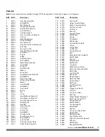
Parts List
Note: Part numbers listed are available through DR Power Equipment. Not all parts appear on all diagrams.
Ref# Part#
Description
1
41522
Gear Box Assembly
2
41686
Bolt M8X20
3
41523
Flat Washer 8
37
41524
Flange Lock Nut M8
63
41525
Engine Shaft Washer
64
41526
Lock Nut M10
65
41527
Counterweight 2
66
41528
Gear Cover Mount Bracket
67
33787
Clip 1.8
68
41529
Right Wheel Assy.
69
41530
Pin Shaft B8x45
70
30250
Flat Washer 10
71
41531
Direction Indicator Weldment
72
41532
Shift Rod
73
41533
Spring Pin 5x30
74
41534
Gear Shift Markable Plate
75
41535
Bolt M6x16
76
41536
Engine
77
41537
Pulley
78
41538
Key B5x4.76x40
79
41539
Screw M8x12
80
41540
Blade Mount Bracket
81
41541
Pin B10x45
82
41542
R Clip 2.5
83
41543
Bolt M10x30
84
41544
Blade 2
85
41545
Swing Nut
86
41546
Adjustable Side Shield B1
87
41547
Bolt M8x20
88
41548
Side Tine Shield
89
41549
B Style Sprig Nut M8
90
41550
Blade 1
91
41551
Lock Nut M8
92
41552
Bolt M8x25
93
41553
Tine Shield
94
41554
Spring
95
41555
Pin
96
41556
C-Clip
97
41557
Handle Mount Bracket 2
98
41558
Handle Mount Bracket 1
99
41559
Handle Support Frame
100 41560
Bolt M10x25
101 41561
Nut M8
102 41562
Upper Handle
103 41563
Lock Lever
104 41564
Lever Knob
105 41565
Bolt M8x85
106 41566
Throttle Cable
107 41567
Throttle Lever Assy.
108 41568
Screw M6x50
109 41569
Lock Nut M6
110 41570
Tensioner Pulley Cable
111 41571
Pulley Cable Drag Rod
Ref# Part#
Description
113 41573
End Cap 25
114 41574
Upper Handle Sleeve
115 41575
Brake Connecting Plate
116 41576
Shift Lever Knob
117 41577
Shift Lever
118 41578
Bushing
119 41579
Support Sleeve
120 41580
Bolt M8x75
121 41581
Spring
122 41582
Pin Bracket
123 41583
Rubber Cap
124 41584
Serrated Rear Shield
125 41585
Hinge
126 41586
Hinge Shaft
127 41587
Limiter Pin
128 41588
Spring Washer 5
129 41589
Bolt
130 41590
Adjustable Side Shield B2
131 41591
Bolt M10x25
132 41592
Spacer 3
133 41593
Screw M5x10
134 41594
Bolt M5x12
135 41595
Long Bolt
136 41596
Cable Fixation Clamp
137 41597
Belt Cover Mount Bracket
138 41598
Belt Pulley
139 41599
Lock Nut M5
140 41600
Key A5x20
141 41601
Depth Stake 3
142 41602
Belt 4LXP1308
143 41603
Depth Stake 2
144 41604
Belt Cover
145 41605
Left Wheel Assy.
146 41606
Spacer 2
147 41607
Flange Lock Nut 10
148 41608
C-Clip 9
149 41609
Tensioner Pulley
150 41610
Bushing
151 41611
Wheel Bracket Weldment
152 41612
Bolt 5/16 - 24 UNF*25
153 41613
Spring Washer 8
154 41614
Bolt M10x290
155 41615
Counterweight 1
156 41616
Bolt M8x40
157 41617
Spacer 1
158 41618
Tensioner Pulley Shaft
159 41619
Bolt M8x30
160 41620
Belt Block Rod
161 41621
Big Flat Washer 8
162 41622
Engine Protector Weldment
163 41623
Spacer 4
164 41624
Bolt M8x16
165 41625
Bearing 6004-2RS


