background image

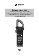
dt202

7

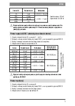
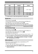
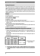
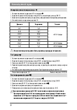
Test ciągłości obwodu  

  1. Ustawić przełącznik funkcji 

O

 na pozycję 

.

  2. Podłączyć czerwony przewód testowy do gniazda V


R

, a czarny przewód do gniazda COM 

N

.

  3. Nacisnąć przycisk SELECT 

L

 aby na wyświetlaczu pojawił się symbol 

.

  4. Przyłożyć przewody pomiarowe do mierzonego obwodu.
  5. Ciągłość obwodu zostanie zasygnalizowana sygnałem dźwiękowym przy oporności < 30 

.

 Przy rezystancji w zakresie 30-100   może pojawić się sygnał dźwiękowy (buzzer). Przy 

rezystancji powyżej 100   sygnał dźwiękowy (buzzer) nie pojawia się   Napięcie testu: 

0,5 V   Zabezpieczenie przeciążeniowe: 250 V DC/AC

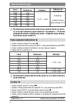
Wymiana baterii i bezpiecznika

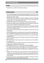
Baterię należy wymienić gdy na wyświetlaczu pojawi się symbol 

.

  1. Zdjąć tylną pokrywę miernika. 
  2. Umieścić nowa baterie 2 x AAA zwracając uwagę na prawidłową polaryzację. 

Gwarancja

Warunki gwarancji zamieszczone są na stronie: http://www.dpm.eu/gwarancja

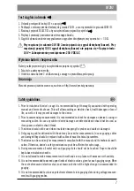
Safety guidelines 

  1. Prior to initiation of device’s usage it is recommended to get thoroughly acquainted with operating 

manual and terms of safe use. This will allow avoiding an electric shock, health damages or loss of 
life, as well as it may prevent damages to the device.

  2. Prior to commencing measurements it is recommended to check for damages on device’s casing or 

measuring cables. In case any cable or device damages are detected device should not be used, as 
it may pose an electric shock threat.

  3. The device should not be used when insulation wrapping the probes and cables is damaged. 
  4. Only gauging cables delivered with the set may be used for measurements. In case gauging cables 

are damaged they should be replaced with cables of exact technical parameters.

  5. The device can be used only for measurements compliant with the manual and its technical specifi

-

cation. Otherwise, device’s safety provisions may not be sufficient for safe usage. 

  6. During measurements all metal ends and gauging slots should not be touched. Fingers should be 

kept above insulation sheaths.

  7. It is not allowed to make measurements with wet hands or in places with excessive air humidity.
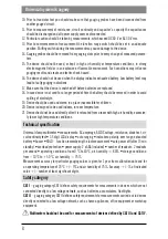
  8. It is not recommended to exceed upper limits of electric values given for each gauging range. When 

the scale of measured electric value is not known selection of the highest range is recommended for 

gauging.

  9. It is not recommended to place any electronic elements into gauging slots during voltage measure

-

ments with gauging probes.

Summary of Contents for DT202

Page 1: ...t202 Uniwersalny miernik c gowy Universal clamp multimeter Digital Zangenmultimeter Skaitmeninis spaustuvo matuoklis Univerz ln up nac multimetr Universa ls skavas multimetrs Universaalne klamberm tur...

Page 2: ......

Page 3: ...ment w elektronicznych w gniazdach pomiarowych urz dzenia podczas pomiaru napi cia przy pomocy sond pomiarowych 10 Przed testem tranzystora nale y upewni si e sondy pomiarowe zosta y od czone od inneg...

Page 4: ...goria pomiarowa CAT II okre la wymagania bezpiecze stwa dla pomiar w przeprowadza nych w urz dzeniach bezpo rednio pod czonych do instalacji niskiego napi cia takich jak urz dzenia domowe biurowe lub...

Page 5: ...o obwodu lub urz dzenia 4 Odczyta warto napi cia na wy wietlaczu M Zakres Rozdzielczo Dok adno Zabezpieczenie przeci eniowe AC 200 mV 0 1 mV 1 2 5 cyfr 600 V DC AC rms Impedancja wej ciowa 10 M Cz sto...

Page 6: ...stowy do gniazda COM N 3 Przy o y przewody pomiarowe do kondensatora zwracaj c uwag na polaryzacj 4 Odczyta warto na wy wietlaczu M Zakres Rozdzielczo Dok adno 4 nF 1 pF 4 0 5 cyfr 40 nF 10 pF 400 nF...

Page 7: ...prevent damages to the device 2 Prior to commencing measurements it is recommended to check for damages on device s casing or measuring cables In case any cable or device damages are detected device s...

Page 8: ...ed and stored in a place inaccessible for children 20 Device is designed to be used indoors in room temperature 21 Device should not be used directly after it is relocated from a room with high air hu...

Page 9: ...A When the display shows 0 the function range switch O should be set to position 2 20 A to obtain adequate resolution 2 Push trigger K open jaws and clamp one connector between the jaws 3 Read the amp...

Page 10: ...ck testing cable to COM socket N 3 Attach gauging cables to measured circuit 4 Read resistance value from the display M range Resolution Accuracy Overload protection 200 0 1 1 5 3 digits 250 DC AC rms...

Page 11: ...it continuity test 1 Set range switch O to position 2 Connect red testing cable to V socket R and the black testing cable to COM socket N 3 Press SELECT button L until symbol will appear on the displa...

Page 12: ...ichen mit hoher Luftfeuchtigkeit durch 8 Die f r jeden Messbereich angegebenen elektrischen Grenzwerte d rfen nicht berschritten werden Wenn die Skala der zu messenden elektrischen Gr e nicht bekannt...

Page 13: ...swerte wird f r den Zeitraum von 1 Jahr nach der Kalibrierung und f r die Betriebstemperatur 23 C 5 C und Luftfeuchtigkeit 75 angegeben Genauigkeit vom Anzeigewert Anzahl der Stellen die am wenigsten...

Page 14: ...ur an einem Leiter des Kabels durchgef hrt werden Spannungsmessung AC DC automatische Messbereichswahl 1 Stellen Sie den Bereichsschalter O in Position V lub V 2 Stecken Sie das rote Messkabel in die...

Page 15: ...aden sind bevor Sie den Widerstand messen Bei Messungen 1 M beno tigt das Messger t einige Sekunden um die Messung zu stabilisieren Bei einem offenen Stromkreis erscheint das OL Symbol auf der Anzeige...

Page 16: ...skabel in die V Buchse R und das schwarze Messkabel in die COM Buch se N ein 3 Die Taste SELECT L dr cken damit auf der Anzeige das Symbol erscheint 4 Bringen Sie die Messkabel an den zu messenden Kre...

Page 17: ...dt202 17 3 4 5 6 7 8 9 10 11 12 DC60 AC30Brms 13 14 15 16 17 18 19 20 21 AC AC DC LCD3 5 buzzer HOLD 2xAAA 2 0 40 C 80 10 C 50 C 75...

Page 18: ...lny miernik c gowy 18 CATI ATI CATII CATII CATIII CATIV O K L SELECT M LCD 3 5 N COM O P HOLD Q MAX R V AC 1 6 200 400A 0 O 2 20A 2 K 3 M 2 A 1 mA 2 5 10 200mV 40 200Hz 20 A 10 mA 2 0 5 200 A 100 mA 4...

Page 19: ...C rms 10 M 40 200 AC 2 V 1 mV 1 2 3 AC 20 V 10 mV 1 2 8 AC 200 V 100 mV DC 200 mV 0 1 mV 0 8 5 600 V DC AC rms DC 2 V 1 mV 0 5 2 DC 20 V 10 mV DC 200 V 100 mV DC 600 V 1 V 1 0 5 DC600V 1 O 2 V R a COM...

Page 20: ...1 O 2 V R a COMN 3 4 M 4nF 1pF 4 0 5 40nF 10pF 400nF 100pF 4 F 1nF 40 F 10nF 400 F 100nF 4 5 5 4mF 1 F 5 0 9 T 1 O 2 V R a COMN 3 SELECTL 4 5 OL 1 5V 250VDC AC 1 O 2 V R a COMN 3 SELECTL 4 5 30 30 10...

Page 21: ...vir izoliuojan i dang 7 Negalima atlikti matavim dr gnomis rankomis ar vietose kuriose yra daug dr gm s 8 Nevir yti kiekvienam elektros matavimo diapazonui nurodyt ribini matavimo ver i Jei matuoja m...

Page 22: ...gm 80 laikymo s lygos nuo 10 C iki 50 C oro dr gm 75 Matavim tikslumas konkre ioms matavimo vert ms pateikiamas 1 met laikotarpiui po kalibravimo ir 23 C 5 C darbo temperat rai ir 75 oro dr gmei Tiksl...

Page 23: ...i diapazono jungikl parinktoje pozicijoje V V 2 Prijunkti raudon bandymo laid prie V lizdo R o juod laid prie COM lizdo N 3 Prid ti matavimo laidus prie matuojamos grandin s ar renginio 4 Perskaityti...

Page 24: ...N 3 Prid ti matavimo laidus prie kondensatorius atkreipti d mes teising poli kum 4 Perskaityti talpyklos kondensatoriaus vert displ juje M Diapazonas Rezoliucija Tikslumas 4 nF 1 pF 4 0 5 skaitmen 40...

Page 25: ...t se p padn mu razu elektrick m proudem ztr t zdrav nebo ivota a tak p edb hne po kozen za zen 2 P ed zah jen m m en je t eba se p esv d it jestli kryt za zen nebo m c kabely nejsou po kozen V p pad j...

Page 26: ...rostorech za pokojov teploty 21 Nelze pou vat za zen p mo po jeho p enesen z m stnosti s vysokou vlhkost vzduchu z n zk nebo vysok teploty Technick specifikace Univerz ln up nac multimetr m en pr toku...

Page 27: ...odnotu pr toku proudu na displeji M Rozsah Rozli en P esnost 2 A 1 mA 2 5 10 slice pokles nap t 200 mV Frekvence 40 200 Hz 20 A 10 mA 2 0 5 slice 200 A 100 mA 400 A 1 A M en proudu se prov d pouze s m...

Page 28: ...10 200 k 100 2 M 1 k 20 M 10 k P ed proveden m en odporu je t eba odpojit nap jen obvodu a ujistit se e v echny kondenz tory jsou vybite P i m en ch 1 M m i pot ebuje n kolik sekund na stabilizaci m e...

Page 29: ...i p et en 250 V DC AC V m na baterie Baterii vym te kdy se na displeji zobraz symbol 1 Sundat zadn kryt m i e 2 Um stit novou baterii 2 x AAA a p esv d it se ze polarizace baterie je spr vn Z ruka Gar...

Page 30: ...truma un gaisa temperat ras apsta k os sp c ga elektromagn tiska lauka spra dzienb stamos vai viegli uzliesmojo os apsta k os a di apsta k i var ietekm t nepareizus m r jumu rezulta tus un novest pie...

Page 31: ...ana pretest bas m r jumi dio u pa rbaude stra vas des nepa rtraukt bas pa rbaude P HOLD p d ja m r juma para d ana displeja noteikta diapazona Q MAX augsta ka s v rt bas m r juma para d ana displeja n...

Page 32: ...10 mV DC 200 V 100 mV DC 600 V 1 V 1 0 5 cipari Nek d gad jum nem rat str vas stiprumu ja atv rtas str vas k des spriegums var p rsniegt zem jumu par DC 600 V Pretest bas m r jumi 1 Iestatiet funkcij...

Page 33: ...du ligzdai COM N 3 Nospiediet tausti u SELECT L lai displeja para d tos simbols 4 Pielieciet sarkano pievadu pie anoda bet melno pievadu pie m ra ma s diodes katoda 5 Nolasiet diodes vad anas spriegum...

Page 34: ...rge m tke m rja k ega ega k rge niiskusega kohtades 8 rge letage iga m tepiirkonna elektriliste suuruste piirv rtusi Kui m detud elektrikomplekti skaala ei ole teada valige m tmise suurim vahemik 9 r...

Page 35: ...vatele seadmetele mis ei ole otseselt hen datud madalpingepaigaldistega n iteks patareid akud taskulambid CAt II kategooria CAT II m rab madala pingega seadeldistega otseselt hendatud seadmete n i tek...

Page 36: ...v i seadmesse 4 Lugege pinge v rtust ekraanil M Valik Resolutsioon T psus U lekoormuskaitse AC 200 mV 0 1 mV 1 2 5 numbrid 600 V DC AC rms Sisendtakistus 10 M Sagedus 40 200 Hz AC 2 V 1 mV 1 2 3 numb...

Page 37: ...M N 3 Kandke testrijuhtmed kondensaatorisse p rates t helepanu polaarsusele 4 Lugege v rtust ekraanilt M Valik Resolutsioon T psus 4 nF 1 pF 4 0 5 numbrid 40 nF 10 pF 400 nF 100 pF 4 F 1 nF 40 F 10 nF...

Page 38: ...Vooluringi j rjepidevuse tagab takistus ja kostub helisignaal 30 Kui takistus on vahemikus 30 100 v ib ilmneda helisignaal buzzer Kui takistus on le 100 ei ilmu helisignaali buzzer Testipinge 0 5 V U...

Page 39: ......

Page 40: ...elektronini prietais nei meskite kartu su buitin mis atliekomis Tinka mas panaudot produkt r iavimas padeda suma inti j neigiam poveik aplinkai ir moni sveikatai Seznamte se s m stn mi pravidly sb ru...

Reviews: