51 / 96
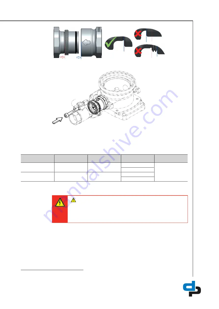
Fig. 23:
Verifying the alignment
13.Verify the correct alignment.
Fig. 24:
Fitting the screw
14.Fit and tighten the screw.
15.Close the drain plugs of the pump. Properly dispose of the fluid collected.
16.Slowly open the shut-off valve and check for any leakage.
Table 21:
Spare parts for servicing non-return valves, per pump
Material number
Description
Non-return valve
O-rings
O-ring lubricant
(non-water soluble)
71630405
ER non-return valve
DN 32
Watts Industries
IN 032 DN 32
1x Eriks 12711456
Molykote ® G-5511
7)
2x Eriks 12711457
71630410
ER non-return valve
DN 50
Watts Industries
IN 050 DN 50
1x Eriks 12192264
2x Eriks 12711459
8.2.6 Mounting the manifold in a mirrored position
DANGER
Voltage at the pressure booster system
Danger to life!
Ø
Prior to opening the device, wait at least 10 minutes for any residual
voltage to dissipate.
1. De-energise the pump set and secure it against unintentional start-up. Comply with the
local regulations.
2. Close the shut-off valves in the discharge line and suction line of the pressure booster
system.
3. Place a suitable container under the drain connections.
4. Open the drain connections. To do so, observe the pump's operating manual.
7
Sealant for taps


