WILDEN PUMP & ENGINEERING, LLC
34
WIL-10161-E-01
PX4 PLASTIC
R U B B E R / T P E - F I T T E D / 3 - P I E C E C E N T E R S E C T I O N
E X P L O D E D V I E W
E X P L O D E D V I E W A N D P A R T L I S T I N G S
Page 1: ...P4 PX4 WIL 10161 E 01 S i m p l i f y y o u r p r o c e s s Engin e e ri n g Operati o n Mainte n a n ce Original Series PLASTIC Pumps...
Page 2: ...tion Lift Curves 15 SECTION 6 SUGGESTED INSTALLATION OPERATION TROUBLESHOOTING 16 SECTION 7 DISASSEMBLY REASSEMBLY A Pump Disassembly 19 B Pro Flo Air Valve Center Section Disassembly 22 C Pro Flo XTM...
Page 3: ...explosion could result Pump valves and containers must be grounded when handling flammable fluids and whenever discharge of static electricity is a hazard CAUTION Do not exceed 8 6 bar 125 psig air s...
Page 4: ...NA N PU POLYURETHANE Brown TV PTFE ENCAP VITON LEGEND P4 XXXXX XXX XX XXX XXXX O RINGS MODEL VALVE SEAT VALVE BALLS DIAPHRAGMS AIR VALVE CENTER BLOCK OR CENTER SECTION AIR CHAMBERS OR CENTER SECTION W...
Page 5: ...the shaft connected to the pressurized diaphragm Diaphragm B is on its suction stroke air behind the diaphragm has been forced out to the atmosphere through the exhaust port of the pump The movement...
Page 6: ...A S 127 DIA 5 0 DIA T 15 DIA 6 DIA DIMENSIONS ITEM METRIC mm STANDARD inch A 394 15 5 B 79 3 1 C 287 11 3 D 465 18 3 E 528 20 8 F 122 4 8 G 295 11 6 H 137 5 4 J 320 12 6 K 411 16 2 L 287 11 3 M 236 9...
Page 7: ...30 psig head pressure Example To pump 159 lpm 40 gpm against a discharge pressure head of 2 7 bar 40 psig requires 4 1 bar 60 psig and 30 6 Nm3 h 18 scfm air consumption See dot on chart Caution Do n...
Page 8: ...ot exceed 8 6 bar 125 psig air supply pressure Flow rates indicated on chart were determined by pumping water For optimum life and performance pumps should be specified so that daily operation paramet...
Page 9: ...PX4 P L A S T I C P X 4 P E R F O R M A N C E...
Page 10: ...bility that exceeds previous industry standards Pro Flo XTM Operating Principal S e c t i o n 5 B Turning the dial changes the relationship between air inlet and exhaust porting Each dial setting repr...
Page 11: ...his case 9 8 scfm Step 2 Determining flow and air X Factors Locate your discharge pressure 40 psig on the verti cal axis of the EMS curve Figure 2 Follow along the 2 8 bar 40 psig horizontal line unti...
Page 12: ...ig discharge pressure After locat ing this point on the flow curve draw a verti cal line downward until reaching the bottom scale on the chart and identify the flow rate In our example it is 38 6 lpm...
Page 13: ...ifferent than the flow point plotted in example 2 1 After estimating or interpolating this point on the curve draw a vertical line downward until reaching the bottom scale on the chart and identify th...
Page 14: ...while the air consumption was reduced by 78 thus providing increased effi ciency For a detailed example for how to set your EMS see beginning of performance curve section Caution Do not exceed 8 6 bar...
Page 15: ...air supply pressure TECHNICAL DATA Height 528 mm 20 8 Width 394 mm 15 5 Depth 320 mm 12 6 Ship Weight Polypropylene 17 kg 37 lbs Air Inlet 19 mm 3 4 Inlet 38 mm 1 1 2 Outlet 38 mm 1 1 2 Suction Lift 4...
Page 16: ...hile the air consumption was reduced by 49 thus providing increased ef fi ciency For a detailed example for how to set your EMS see beginning of performance curve section Caution Do not exceed 8 6 bar...
Page 17: ...t is meant to be a guide only There are many variables which can affect your pump s operating characteristics The number of intake and discharge elbows viscosity of pumping fluid elevation atmospheric...
Page 18: ...n multiplying the figure by the displacement per stroke MUFFLER Sound levels are reduced below OSHA specifications using the standard Wilden muffler Other mufflers can be used to further reduce sound...
Page 19: ...to the pump therefore stopping output This shut off valve should be located far enough away from the pumping equipment such that it can be reached safely in an emergency situation NOTE In the event of...
Page 20: ...ghtness of outer pistons to shaft OPERATION The P4 and PX4 pumps are pre lubricated and do not require in line lubrication Additional lubrication will not damage the pump however if the pump is heavil...
Page 21: ...pump should be disconnected and all air pressure allowed to bleed from the pump Disconnect all intake discharge and air lines Drain the pump by turning it upside down and allowing any fluid to flow i...
Page 22: ...Step 8 Figure 8 Remove small manifold clamp bands to inspect manifold o rings Step 4 Figure 4 Remove the discharge valve balls and seats from the liquid chambers and inspect for nicks gouges chemical...
Page 23: ...om the center section Figure 12 2 The outer piston diaphragm and inner piston separate from the shaft which remains connected to the opposite side diaphragm assembly Figure 13 Repeat disassembly instr...
Page 24: ...t all intake discharge and air lines Drain the pump by turning it upside down and allowing any fluid to flow into a suitable container Be aware of hazardous effects of contact with your process fluid...
Page 25: ...Glyd rings for signs of wear If necessary remove Glyd rings with o ring pick and replace NOTE Threaded sleeves see A Figure 10 are removable and can be replaced if necessary Sleeves can be press fit...
Page 26: ...by threading one air valve bolt into the end of the spool and gently sliding the spool out of the air valve body Inspect seals for signs of wear and replace entire assembly if necessary Use caution w...
Page 27: ...of the center hole cut on the spool Gently remove the pilot spool from sleeve and inspect for nicks or gouges and other signs of wear Replace pilot sleeve assembly or outer sleeve o rings if necessary...
Page 28: ...seal in hand place the two legs of the needle nose pliers inside the seal ring See Figure A Open the pliers as wide as the seal diameter will allow then with two fingers pull down on the top portion...
Page 29: ...stretch the tape during placement in center of diaphragm bead groove Step 3 Figure 3 The ends of the tape should overlap approximately 13 mm 1 2 Proceed to install the PTFE tape on the remaining liqu...
Page 30: ...WILDEN PUMP ENGINEERING LLC 28 WIL 10161 E 01 P4 PLASTIC RUBBER TPE FIT TED 3 PIECE CENTER SECTION EXPLODED VIEW S e c t i o n 8 E X P L O D E D V I E W A N D P A R T L I S T I N G S...
Page 31: ...03 04 3890 03 04 3890 03 04 3890 03 20 Inner Piston 2 04 3700 01 700 04 3700 01 700 04 3700 01 700 04 3700 01 700 21 Diaphragm 2 22 Outer Piston 2 04 4550 20 500 04 4550 21 500 04 4550 20 500 04 4550...
Page 32: ...WILDEN PUMP ENGINEERING LLC 30 WIL 10161 E 01 P4 PLASTIC P T F E F I T T E D 3 P I E C E C E N T E R S E C T I O N E X P L O D E D V I E W E X P L O D E D V I E W A N D P A R T L I S T I N G S...
Page 33: ...04 3750 01 700 21 Back up Diaphragm 2 04 1060 51 04 1060 51 04 1060 51 04 1060 51 04 1060 51 04 1060 51 22 Diaphragm PTFE 2 04 1010 55 04 1010 55 04 1010 55 04 1010 55 04 1010 55 04 1010 55 23 Outer P...
Page 34: ...WILDEN PUMP ENGINEERING LLC 32 WIL 10161 E 01 P4 PLASTIC 1 P I E C E C E N T E R S E C T I O N E X P L O D E D V I E W E X P L O D E D V I E W A N D P A R T L I S T I N G S...
Page 35: ...0 04 4550 21 500 04 4600 20 500 04 4600 21 500 04 4600 22 500 20 Valve Seat 4 04 1120 20 500 04 1120 21 500 04 1120 20 500 04 1120 21 500 04 7305 03 21 Valve Seat O Ring 2 609 x 139 4 04 1200 60 500 0...
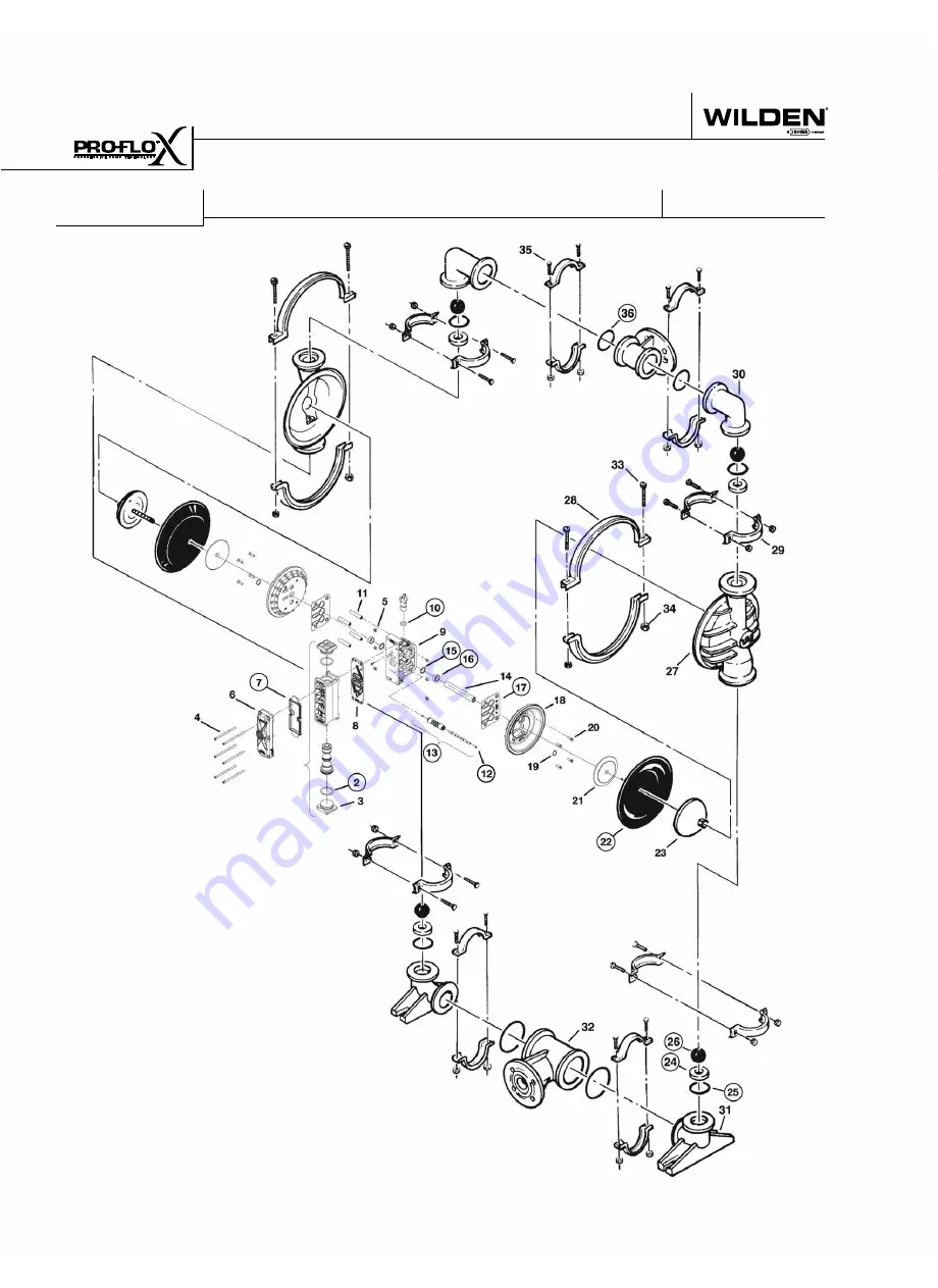
Page 36: ...WILDEN PUMP ENGINEERING LLC 34 WIL 10161 E 01 PX4 PLASTIC RUBBER TPE FIT TED 3 PIECE CENTER SECTION EXPLODED VIEW E X P L O D E D V I E W A N D P A R T L I S T I N G S...
Page 37: ...4 3890 03 04 3890 03 04 3890 03 04 3890 03 20 Screw Custom HSFCHC 3 8 16 x 1 00 8 71 6250 08 71 6250 08 71 6250 08 71 6250 08 21 Inner Piston 2 04 3700 01 700 04 3700 01 700 04 3700 01 700 04 3700 01...
Page 38: ...WILDEN PUMP ENGINEERING LLC 36 WIL 10161 E 01 PX4 PLASTIC P T F E F I T T E D 3 P I E C E C E N T E R S E C T I O N E X P L O D E D V I E W E X P L O D E D V I E W A N D P A R T L I S T I N G S...
Page 39: ...06 13 17 Gasket Center Block Pro Flo V 2 04 3529 52 04 3529 52 04 3529 52 04 3529 52 18 Air Chamber Pro Flo V 2 04 3660 01 04 3660 01 04 3660 05 04 3660 05 19 Retaining Ring 2 04 3890 03 04 3890 03 04...
Page 40: ...iton N A N A N A 04 1200 60 500 04 1300 60 500 Neoprene Backup 04 1060 51 N A N A N A N A Polyurethane 04 1010 50 04 1080 50 N A 04 1200 50 500 04 1300 50 500 Saniflex 04 1010 56 04 1080 56 N A N A N...
Page 41: ...comes rst Failure due to normal wear misapplication or abuse is of course excluded from this warranty Since the use of Wilden pumps and parts is beyond our control we cannot guarantee the suitability...