


3 7
P
OWER
AND
C
OMMUNICATION
3.
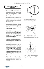
Install the supplied snap bushing
into the access hole that carries the
power and phone cords. Install the
supplied dome plug into the
unused access hole.
See Figure 3 for an example that shows
the snap bushing on the rear access
hole and the dome plug on the side
access hole.
4.
Plug the AC power plug into the
wall outlet.
5.
Plug the phone cord into the wall
mounted modular phone jack.
**IMPORTANT**
The AC socket outlet shall be in-
stalled near the equipment and shall
be easily accessible.
Figure 3. Install snap bushing on
access hole that carries power
and phone cords. Install dome
plug on unused access hole.
Figure 2b. Power and phone cords
routed through side access hole.
Figure 2a. Power and phone cords
routed through rear access hole.
POWER OUTLET
ACCESSIBILITY
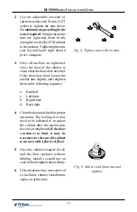
Whether you are installing a new
outlet, or plan to use an existing
outlet to supply power to the ATM,
make sure the following require-
ments are met:
1.
The outlet is located near the
cabinet.
2.
The outlet is easily accessible.
3.
Access to the outlet will not be
blocked once the cabinet is in-
stalled!
**IMPORTANT**
The phone line used for the ATM
shall not be shared with any other
device!
Summary of Contents for Triton RL5000 Series
Page 7: ...7 ATM INSTALLATION FOR ACCESSIBILITY ...
Page 14: ...14 THIS PAGE INTENTIONALLY LEFT BLANK ...
Page 15: ...15 ATM ENVIRONMENTAL PRECAUTIONS CHECKLIST ...
Page 17: ...17 CABINET INSTALLATION STANDARD ANCHORS ...
Page 24: ...24 RL5000 SERIES INSTALLATION GUIDE THIS PAGE INTENTIONALLY LEFT BLANK ...
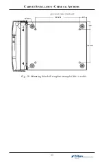
Page 25: ...CABINET INSTALLATION CHEMICAL ANCHORS 21 ...
Page 34: ...34 THIS PAGE INTENTIONALLY LEFT BLANK ...
Page 35: ...35 POWER AND COMMUNICATION ...
Page 38: ...38 THIS PAGE INTENTIONALLY LEFT BLANK ...
Page 39: ...39 TDM 100 150 DISPENSING MECHANISM INSTALLATION ...
Page 44: ...44 THIS PAGE INTENTIONALLY LEFT BLANK ...
Page 45: ...45 SDD DISPENSING MECHANISM INSTALLATION ...