2 1
LEVEL FLOORING REQUIRE-
MENT
It is very important that the ATM
cabinet be located on flat, level
flooring! If the floor is not flat
and level the cabinet bottom and/
or walls may become distorted
when the mounting bolts are tight-
ened down! This could prevent
the security vault door from clos-
ing!
BOLT CABINET TO FLOOR
LEVELING FEET
The leveling feet included in the
cabinet installation kit are for op-
tional use with the Business
Hours Service cabinet.
Follow these steps to install and
adjust the leveling feet:
1.
Screw the leveling feet
completely into the four
threaded bosses in the base
of the cabinet. If necessary,
lay the cabinet on its side
to access the bosses.
2.
Once the cabinet is in the
final mounting position use
a screwdriver to adjust the
leveling bolts. DO NOT
extend the feet any further
than necessary to level the
cabinet! Use a bubble
level, if available, to verify
the cabinet is level.
3.
After the mounting bolts
have been tightened,
ensure the cabinet door can
close without binding. It
may be necessary to adjust
the tightening of the
mounting bolts to enable
the door to close without
binding.
If leveling feet are used, the cabi-
net bottom may experience warp-
ing or bending when the mount-
ing bolts are tightened down!
This may prevent the cabinet
door from closing cleanly!
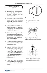
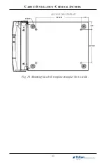
1.
Move the ATM into position for
mounting by aligning the base over
the four holes drilled in the
previous procedure.
2.
Place an anchor bolt through the
cabinet base and into one of the
mounting holes. Use a ball peen
hammer to tap the bolt completely
into the hole.
IMPORTANT: If the anchor bolt
“falls” into the hole without
needing to be tapped in, the hole
is too large! The mounting-hole
pattern will have to be moved and
redrilled using smaller holes as
necessary to achieve a snug fit.
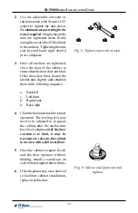
3.
Place a flat washer on the anchor
bolt followed by a 3/8” nut.
4.
Repeat Steps 2 and 3 for the
remaining anchor bolts.
C
ABINET
I
NSTALLATION
- S
TANDARD
A
NCHORS
Summary of Contents for Triton RL5000 Series
Page 7: ...7 ATM INSTALLATION FOR ACCESSIBILITY ...
Page 14: ...14 THIS PAGE INTENTIONALLY LEFT BLANK ...
Page 15: ...15 ATM ENVIRONMENTAL PRECAUTIONS CHECKLIST ...
Page 17: ...17 CABINET INSTALLATION STANDARD ANCHORS ...
Page 24: ...24 RL5000 SERIES INSTALLATION GUIDE THIS PAGE INTENTIONALLY LEFT BLANK ...
Page 25: ...CABINET INSTALLATION CHEMICAL ANCHORS 21 ...
Page 34: ...34 THIS PAGE INTENTIONALLY LEFT BLANK ...
Page 35: ...35 POWER AND COMMUNICATION ...
Page 38: ...38 THIS PAGE INTENTIONALLY LEFT BLANK ...
Page 39: ...39 TDM 100 150 DISPENSING MECHANISM INSTALLATION ...
Page 44: ...44 THIS PAGE INTENTIONALLY LEFT BLANK ...
Page 45: ...45 SDD DISPENSING MECHANISM INSTALLATION ...


