Dover MOUVEX ASX40 Instructions Manual Download Page 6

6/19

NT 1101-G00 08.10 AX40 - ASX40 e

If the liquid may freeze or solidify, prepare for draining
the piping by installing drain taps at the low points and
air vents at the high points.

In the case of a very high intake or if you wish to prevent
the piping from emptying at shutdown, you can install a
foot valve. It should have a large diameter so as not to
generate additional head loss.

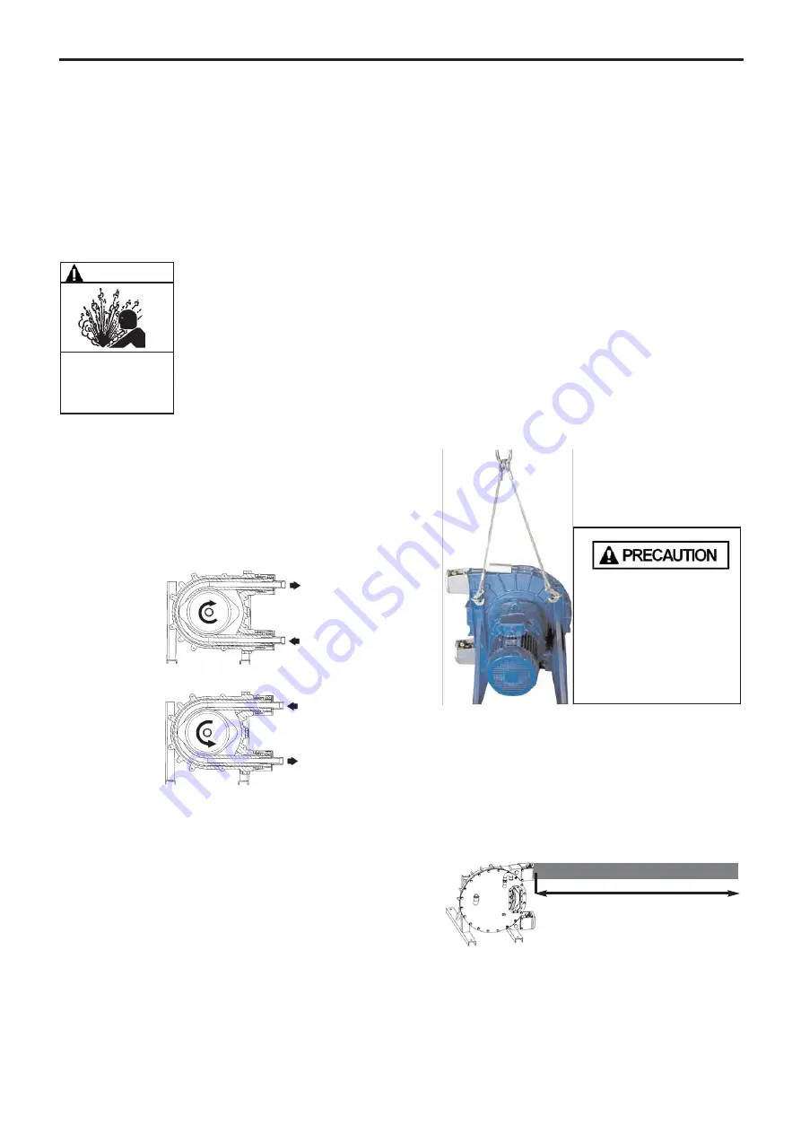
2.6 Direction of  rotation

The MOUVEX pump is reversible, this allows it to always
circulate the liquid in the desired direction by choosing
the corresponding direction of rotation.

The intake and discharge sides are determined as follows :

When an observer is placed on pump cover side (oppo-
site to the shaft output), if rotation takes place clockwise,
the intake is on the bottom, on the contrary if the rotation
is anticlockwise, the intake is on the top.

2.7 Liquids containing a high proportion of

particles

In the case where the pumped fluid contains particles,
use the upper flange as the inlet flange.

This facilitates discharge of the sediments formed by the
build-up of the particles contained in the fluid, so this
reduces friction between the hose and the shoes.

Therefore, the pump may be re-started more easily.

2.8 Working with vaccum on the suction side

Because of the operating principle of the pump, using it
with suction pressure lower than the atmospheric pres-
sure will cause a resulting loss of flow more or less in
line with the conditions of the application (hose material,
rotation speed, temperature, etc.).

In order for the pump to generate the normally required
flow, MOUVEX recommends using a vacuum draw kit
inside the body of the pump.

In all cases, when using a vaccum kit, suction pressure
must not be lower than -0,9 barg (-13 psig).

If a vacuum draw kit is not used on an ABAQUE pump
operating with suction pressure lower than atmospheric
pressure, MOUVEX no longer guarantees the perfor-
mance of the pump.

2.9 Handling

The maximum weight of the pump is :

• AX40 ..............................200 kg (441 lb)
• ASX40 ............................130 kg (287 lb)

2.10 Pump location

Provide sufficient clearance around the pump for main-
tenance operations.

Particularly, make sure that there is sufficient clearance
for replacing the hose; the distance between the pump
flanges and the closest obstacle must allow the hose to
be removed, as shown below :

Clockwise rotation

Anticlockwise rotation

1200 mm (47,244 in)

USE SUITABLE LIFTING
DEVICES FOR HANDLING.

USE THE LIFTING RINGS
PROVIDED.

FAILURE TO RELIEVE THE SYSTEM
PRESSURE PRIOR TO PERFORMING
ANY WORK ON THE PUMP OR THE
INSTALLATION CAN CAUSE PERSONAL
INJURY OR PROPERTY DAMAGE.

WARNING

Hazardous pressure 

can cause 

personal injury 

or property damage.

2. INSTALLATION (continued)

Summary of Contents for MOUVEX ASX40

Page 1: ...August 2010 Replaces July 2010 Original instructions Your distributor Z I La Plaine des Isles F 89000 AUXERRE FRANCE Tel 33 0 3 86 49 86 30 Fax 33 0 3 86 49 87 17 contact mouvex com www mouvex com 3 Poruchik Nedelcho Bonchev Str fl 5 1528 Sofia Bulgaria tel 359 2 973 27 67 e mail office daisglobal eu ...

Page 2: ...r major property damage Warns of hazards that WILL cause serious personal injury death or major property damage Warns of hazards that CAN cause serious personal injury death or major property damage Warns of hazards that CAN cause personal injury or property damage NOTICE Indicates special instructions which are very important and must be followed SAFETY INFORMATIONS WARNING CAUTION DANGER NOTES T...

Page 3: ...AX40 model 1 OVERALL DIMENSIONS with PN16 flanges with PN20 flanges with PN16 flanges A 1 4 with PN20 flanges A 1 4 4 holes Thermal sensor emplacement to choose according rotation direction see ATEX Instructions Pump plate S P 4 holes 4 holes ...

Page 4: ...model 1 OVERALL DIMENSIONS continued with PN16 flanges with PN20 flanges with PN16 flanges A 1 4 with PN20 flanges A 1 4 4 holes Thermal sensor emplacement to choose according rotation direction see ATEX Instructions Pump plate S P 4 holes 4 holes ...

Page 5: ...remains within design limits Therefore it is difficult to give general and precise directions However we recall that it is never prejudicial to plan for wide piping diameters particularly regarding the intake For the discharge it is also possible to plan for a diame ter equal to that of the pump s orifices and on the inta ke for a wider diameter if suction is very strong In the case of viscous pro...

Page 6: ...n the suction side Because of the operating principle of the pump using it with suction pressure lower than the atmospheric pres sure will cause a resulting loss of flow more or less in line with the conditions of the application hose material rotation speed temperature etc In order for the pump to generate the normally required flow MOUVEX recommends using a vacuum draw kit inside the body of the...

Page 7: ...t be protected by appropriate circuit breakers and fuses Connect the regulatory ground connections Check the direction of rotation This fundamental checking of the pump must be done without any product with the inlet and outlet circuit open to the air for example to avoid any risk of an unexpec ted pressure rise Start the pump empty to check the cor rect operation of the connections and check that...

Page 8: ...is necessary to ensure that the consistency of the deposi ted products will not affect the start up of the pump 3 5 Starting up the pump Before starting up the pump always ensure that the pum ping conditions are correct with the corresponding valves open especially the inlet valve For use at temperatures below 0 C 32 F specific pre cautions must be taken Refer to LUBRICATION 3 6 Shutting down the ...

Page 9: ...e clamp 9 8 Remove the hose clamp 8 9 Remove the hose clamp 7 10 Remove the nipple 6 NOTES To insure an optimal life cycle of the hose it is recom mended to replace the worn lubricant by some new lubricant during any replacement of hose The hose may contain a certain volume of the pumped fluid but this will be expelled when restarting the pump Evacuation of this fluid may also be carried out by ru...

Page 10: ... the inlet port of the pump body 1 4 Operate the pump intermittently until the hose 16 is completely inserted in the body 1 so that the same length protrudes from both ports of the body WARNING Do not operate without guard in place NEVER INSERT THE HOSE OR RUN THE PUMP WITHOUT ITS COVER AND ITS WIN DOW IN PLACE 16 1 WARNING The weight ot the parts can be dangerous and may provoke bodily injuries o...

Page 11: ...gainst the flange 47 12 Tighten the hose clamp 8 the screw should be tigh tened to the stop onto the nipple 6 13 Tighten the hose clamp 9 the screw should be tigh tened to the stop onto the hose 16 TOP PORT Repeat the previous steps from 1 to 13 4 1 5 FILLING WITH LUBRICANT 1 Loosen the plug 124 2 Fill the pump body with the lubricant see LUBRICATION 3 Screw the plug 124 Run the pump for a few min...

Page 12: ...ightly tighten screws 20a 7 Slide wheel 3 on the reduction gear or the bearing box shaft 8 Align wheel 3 with pump body 1 while keeping setting distance as indicated on the following diagram 9 Gradually tighten screws 20a while keeping wheel alignment correct 4 3 Replacing the shoes To replace the shoes 5 the pump hose must be disas sembled see REPLACING THE HOSE 4 3 1 DISASSEMBLING THE SHOES 1 Pa...

Page 13: ...tedly 3 Drain the pump of his lubricant following the instruc tions of the DISASSEMBLING THE HOSE 4 Loosen the screws 37 and remove the washers 38 5 Remove the window 15 6 Remove the window seal 46 7 Partially untighten the screw 28 8 Place the suitable number of shims 4 see SHIMMING THE SHOES 9 Tighten the screw 28 check that the shoe 5 is correctly aligned with the wheel 3 see ASSEMBLING THE SHO...

Page 14: ...dicated in LUBRICATION 3 Screw the plug 124 NOTES Handle the lubricant with care Wear suitable clothes and protect yourself from pump lubricant spatters THEPUMPLUBRICANTISVERYSLIPPERY AND MAY CAUSE SERIOUS INJURY ANY SPILLS MUST BE CLEANED UP CAUTION Slippery lubricant Spills should be cleaned up 4 MAINTENANCE OPERATIONS continued ...

Page 15: ... 10000 15000 20000 25000 0 8 1 6 2 4 3 2 4 0 4 8 5 6 6 4 7 2 8 0 8 8 9 6 Flowrate m3 h Max viscosity cps 5 bar 7 5 bar 10 bar 15 bar Continuous service Intermittent service Max service 122 F Max service 140 F Max service 158 F Max service 176 F 0 1 2 3 4 5 6 10 20 30 40 50 60 70 80 90 100 110 120 Rotation speed rpm Motor power US HP 0 10000 20000 30000 40000 50000 60000 70000 80000 90000 100000 3 ...

Page 16: ... for a service pressure up to 5 bar 72 5 psi For higher pressure value one or more removable shims must be placed under the shoes Similarly for using the equipment at a lower service pressure one or more removable shims should be removed from below the shoes The number of removable shims to be added to the pre shimming shims is specified in the table below 5 2 3 PUMP NOT PRE SHIMMED IN THE FACTORY...

Page 17: ...nitored so that it can be replaced before any breakdown should occur Preventive replacement is advisable Temperature threshold values for the liquid pumped depend directly on the materials that make up the hose Refer to technical characteristics on the cover page for the corresponding values It is important to note that the temperature of the pumped liquid influences the limits of use of the pump ...

Page 18: ...ssure drop at inlet Check the inlet line see 2 4 PIPE DIAMETERS WEAK FLOW The pump hose is damaged Replace the hose see 4 1 REPLACING THE HOSE The lubricant is not suitable Empty the pump body and replace the lubricant with one that is recommended by MOUVEX The lubricant is dirty or too old Empty the pump body and replace the lubricant with a new MOUVEX lubricant Temperature of the pumped fluid is...

Page 19: ...1672 2 2009 NF EN ISO 13857 2008 NF EN 12162 2009 x ATEX Directive 94 9 EC 23 march 1994 as transposed by the national legislation concerning equipment intended to be used in explosive atmospheres Conformity obtained by application of the standards NF EN 1127 1 1997 NF EN 13463 1 2009 NF EN 13463 5 2009 ATEX Certification delivered by INERIS Notified Body INERIS Parc Technologique Alata 60550 Vern...

Reviews: