background image

  5 


System Layout 


2.2   

Rear Panel Layout 


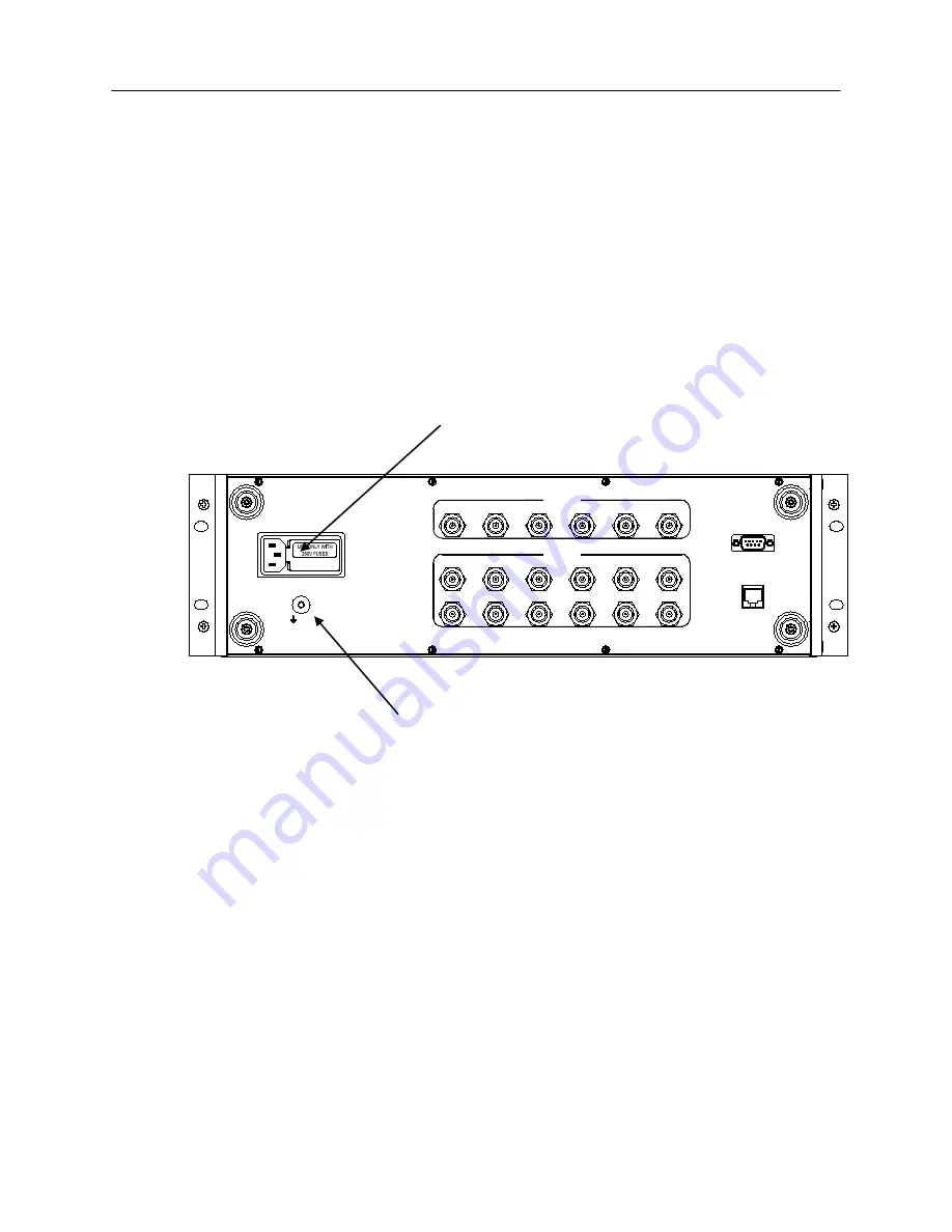
Figure 2-2 shows the general layout of the rear panel of the Model 3205 which 
includes: 

  BNC-Precision Female Connectors


  Power Entry Module with built in Fuse


  RJ-45 Connector


  DB9 Female Connector


  Chassis Ground


Figure 2-2   


Rear Panel  Layout   


Line Fuse 


GND

MAC ADDRESS:

ETHERNET

RS-232

DISCONNECT POWER

BEFORE REPLACING FUSES

OUTPUTS

OUTPUT 1

OUTPUT 7

OUTPUT 2

OUTPUT 8

OUTPUT 3

OUTPUT 9

OUTPUT 4

OUTPUT 10

OUTPUT 5

OUTPUT 11

OUTPUT 6

OUTPUT 12

INPUTS

INPUT 1

INPUT 6

INPUT 3

INPUT 2

INPUT 4

INPUT 5


Power Entry Module 

Summary of Contents for Dow-Key Microwave 3205

Page 1: ...Model 3205 Solid State Matrix System Operation Manual Document No 49101 130 Rev 1 ...

Page 2: ...2004 All rights reserved Information in this publication supercedes that in all previously published material Specifications and price change privileges reserved Printed in the U S A Dow Key is a registered trademark of Dow Key Microwave Corp ...

Page 3: ...d return instructions Send the product transportation prepaid to the Dow Key headquarters Repairs will be made and the product returned within the quoted period of time transportation prepaid Repaired or replaced products are warranted for the balance of the original warranty period or at least 90 days NEITHER DOW KEY MICROWAVE CORPORATION NOR ANY OF ITS EMPLOYEES SHALL BE LIABLE FOR ANY DIRECT IN...

Page 4: ... Addendums are released between revisions and contain important change information that the user should incorporate immediately into the manual When a new revision is created all addendum associated with the previous revision of the manual are incorporated into the new revision of the manual Each new revision includes a revised copy of this history page Revision 1 Document Number 49101 130 Decembe...

Page 5: ...und Connection 8 4 Configuring the Matrix 4 1 Configuring the Matrix 9 4 2 MAC Address 9 4 3 Ethernet Connections 9 4 4 Turning on the Unit 10 4 5 Calibrating the Touch Screen 10 4 6 Testing the Ethernet Connections 10 4 7 Communication Problems 11 4 8 Power Failure 11 5 Manual Local Operation 5 1 Front Panel Controls 12 5 2 Manual Operation using the Touch Screen 13 5 3 Setting Multiple Outputs t...

Page 6: ...2 1 Front Panel Layout 4 2 2 Rear Panel Layout 5 2 3 Schematic Layout 6 3 1 Power Entry Module 8 5 1 Front Panel Controls 12 5 2 Output 5 connected to Input 3 13 5 3 Output 2 5 and 8 connected to Input 3 14 5 4 Output 5 disconnect from Input 3 15 5 5 Setup Main Screen 16 5 6 Change Line Colors 17 5 7 Change Output Names 18 5 8 Change Input Names 19 5 9 Change Network Name 20 5 10 IP Address Screen...

Page 7: ...nput with a touch of the screen Also included with the Model 3205 is Ethernet and RS 232 control 1 2 Specifications Configuration 6 inputs connected to 12 outputs RF Connectors 18 BNC Female connectors Impedance 50 Ohms Frequency Range 2 0 32 0 MHz Isolation 50dB input input 50dB input output 50dB output output different input 30dB output output common input VSWR 1 8 1 Input 1 8 1 Output Gain 0 dB...

Page 8: ... should be observed before using this product and any associated instrumentation This product is intended for use by qualified personnel who recognize the safety precautions required to avoid possible injury 1 4 Inspection The Model 3205 was carefully inspected both electrically and mechanically before shipment After unpacking all items from the shipping carton check for any obvious signs of physi...

Page 9: ...1 6 Repacking for shipment Should it become necessary to return the Model 3205 for repair carefully pack the unit in its original packing carton or the equivalent and follow these instructions Call the Repair Department at 1 805 650 2325 for a Return Material Authorization RMA number Advise as to the warranty status of the Model 3205 Write ATTENTION REPAIR DEPARTMENT and the RMA number on the ship...

Page 10: ...itor Dual Color LED s for power supply monitoring Removable hard disk drive Power Switch with a switch guard Figure 2 1 Power Switch LED s for Power Front Panel Layout with Guard Supply Monitoring SUPPLY 2 SUPPLY 1 MODEL 5042 RANGE HF MATRIX SWITCH 2 32 MHZ Dow Key Microwave CORPORATION A COMPANY DOVER 6X12 HIGH DYNAMIC Touch Screen Removable Hard Drive ...

Page 11: ...e with built in Fuse RJ 45 Connector DB9 Female Connector Chassis Ground Figure 2 2 Rear Panel Layout Line Fuse GND MAC ADDRESS ETHERNET RS 232 DISCONNECT POWER BEFORE REPLACING FUSES OUTPUTS OUTPUT 1 OUTPUT 7 OUTPUT 2 OUTPUT 8 OUTPUT 3 OUTPUT 9 OUTPUT 4 OUTPUT 10 OUTPUT 5 OUTPUT 11 OUTPUT 6 OUTPUT 12 INPUTS INPUT 1 INPUT 6 INPUT 3 INPUT 2 INPUT 4 INPUT 5 Power Entry Module ...

Page 12: ...6 System Layout 2 3 Schematic Layout Figure 2 3 Simplified Schematic OUT 10 OUT 11 OUT 12 IN 1 IN 2 IN 3 IN 4 IN 5 IN 6 OUT 1 1 OUT 2 2 OUT 3 3 OUT 4 4 OUT 5 5 OUT 6 6 OUT 7 7 OUT 8 8 OUT 9 9 10 11 12 ...

Page 13: ...lure to use a grounded outlet may result in personal injury or death due to electric shock 3 1 3 Line Fuse Replacement A rear panel fuse protects the power line input of the Model 3205 If the line fuse needs replacement perform the steps below WARNING Disconnect the line cord from the unit before changing the line fuse 1 The fuse is located in a holder in the power module unit above the AC recepta...

Page 14: ...EPLACING FUSES Table 3 1 Line Fuse Line Voltage Fuse Rating Manufacturer Manufacturer Part No 120 240V 2A Slo Blo 250V x 1 1 4 Littelfuse 312002 3 2 Ground Connection The rear panel ground screw figure 2 2 should be connected to safety earth ground using 18 AWG or larger wire if the Model 3205 is not mounted in a properly grounded rack ...

Page 15: ...p Network Name and look under Port Number CAUTION It is important that no two devices are assigned the same IP address Both devices may fail to communicate on the network To set the TCP port from the touch screen refer to section 5 6 5 4 2 MAC Address Your matrix has a unique built in MAC address associated with the Ethernet card inside the matrix The MAC address is a 48 bit number assigned at the...

Page 16: ...een is now calibrated Note To ensure proper operation of the touch screen the calibration procedure must be performed each time the unit is turned off and then back on 4 6 Testing the Ethernet Communication You should now test the communication between your computer and your matrix The ping utility is typically used to test this communication Enter the following at the command prompt of a DOS wind...

Page 17: ...ntact your network administrator for additional assistance If your network administrator is unable to locate the problem please contact Dow Key Microwave Corporation at 1 805 650 2325 4 8 Power Failure If a power failure should occur the matrix upon power up will set switches to last settings before the failure Once the computer resets and the Dow Key Microwave program is opened all paths should b...

Page 18: ...rols Once the unit has booted up to the windows screen Click onto the DOW KEY MICROWAVE ICON The display will show a grid with Outputs 1 through 12 on the left and Inputs 1 through 6 along the bottom as shown in Figure 5 1 Figure 5 1 Start up display ...

Page 19: ...hich output you desire then click on the input path you desire A line will appear showing the connection you requested Lets say you want to select output 5 to input 3 First you will touch the screen where it says output 5 on the left and then touch the screen again where is says input 3 The screen should show a connection from output 5 to input 3 as shown in figure 5 2 Figure 5 2 Output 5 connecte...

Page 20: ...a single input Lets say you also want to set output 2 to input 3 and output 8 to input 3 Using the say procedure as stated in 5 2 first click onto output 2 and then input 3 followed by clicking on output 8 to input 3 The screen will appear as shown in Figure 5 3 Figure 5 3 Output 2 5 and 8 connected to Input 3 ...

Page 21: ...nect Lets say you want to disconnect Output 5 from Input 3 First click on Output 5 and then on Input 3 and the path will disconnect as shown in Figure 5 4 Figure 5 4 Output 5 disconnected from Input 3 5 5 Clear All To clear all paths click on the CLEAR ALL green button in the upper right corner of the screen This will clear all paths back to the open state ...

Page 22: ... the user can define the following parameters and as shown in Figure 5 5 1 Change the color of the inputs 2 Reassign the Output names 3 Reassign the Input names 4 Assign a Network name and port number 5 Assign an IP Address Figure 5 5 Setup Main Screen ...

Page 23: ...the colors of the connection lines go to the setup button in the upper right hand corner There are 8 inputs each with their own color To change a color of an input line click on that input and choose a new color See Figure 5 6 Figure 5 6 Change Line Colors ...

Page 24: ...utput Names go to the setup button in the upper right corner of the touch screen and click on the Output Names tab Click inside the box you wish to change and type in the new name See Figure 5 7 Note Maximum number of characters is 6 Figure 5 7 Change Output Names ...

Page 25: ...Input Names go to the setup button in the upper right corner of the touch screen and click on the Input Names tab Click inside the box you wish to change and type in the new name See Figure 5 8 Note Maximum number of characters is 3 Figure 5 8 Change Input Names ...

Page 26: ...creen and click on the Network Name tab It will give you the current network name and down below gives you the option to change and type in the new name See Figure 5 9 Figure 5 9 Change Network Name 5 6 4 1 Port Number To set your port number click on box labeled port number and enter the number given to you by your network administrator ...

Page 27: ...ess click on the setup button in the upper right corner and click on the IP Address tab There are two network settings to choose from Obtain IP Address automatically or Use an IP Address given by your network administrator See Figure 5 10 Figure 5 10 IP Address Screen ...

Page 28: ...t separately i e send ROUTE PATH3 then return OPC 6 2 Shortcuts Keywords may be used in their short or verbose form A list of commands and their associated short form is listed below None of the commands are case sensitive The user is free to send upper or lower case commands 1 ROUT ROUTE 2 SYST SYSTEM 3 ERR ERROR 6 3 ROUTE PATHx y Syntax ROUTE PATHx y X Input Y Output Description If output y is c...

Page 29: ...x ROUTE PATH ALL Description This command will return all path pairs separated by a semicolon PATHx y PATHx y PATHx y X Input Y Output 6 6 IDN Syntax IDN Result A string is returned which consists of the following parts Vendor model firmware revision serial number vendor Name of the vendor description Instrument description firmware revision Revision state of the instrument firmware serial number ...

Page 30: ...d configuration information similar to power cycling 6 8 SYSTEM HARDRESET Syntax SYSTEM HARDRESET Description This command is the hard reset This will cause the unit to be forcibly reset returning everything to a factory delivered default mode of operation 6 9 SYSTEM ERROR Syntax SYSTEM ERROR Description This command will return either 0 NO ERROR or will return useful error messages to aid in the ...

Reviews: