Douglas Dynamics Western Striker 98805 Owner'S Manual Download Page 11

Lit. No. 74125/74126, Rev. 00 

11 

July 1, 2020

DETERMINING VEHICLE PAYLOAD

1.  Install the hopper spreader and optional 

equipment according to the Installation 

Instructions.

2.  Install or attach any other equipment that will be 

on the vehicle while the hopper spreader will be in 

use (step bumper, trailer hitch, snowplows, etc.). 

Fill gas tanks.

3.  Obtain the Gross Vehicle Weight Rating (GVWR), 

Front Gross Axle Weight Rating (FGAWR), and 

Rear Gross Axle Weight Rating (RGAWR) from 

the certification label located inside the driver-side 

door jamb or door.

4.  With the occupants in the truck for normal hopper 

spreader operation, weigh the vehicle to obtain 

gross vehicle weight (GVW).

5.  Subtract the GVW from the GVWR to determine 

the available material payload.

6.  Obtain the weight per cubic yard (lb/yd

3

) of the 

desired material. Divide the weight into the 

payload to determine the maximum volume of 

material that can be carried.

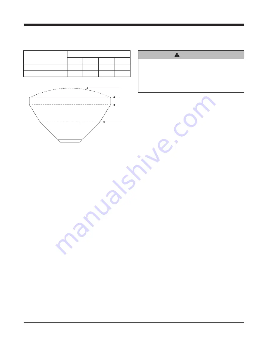
7.  Refer to the Load Volume table and diagrams to 

determine the maximum fill level for the material.

8.  Fill the hopper with material to the calculated level. 

Reweigh the vehicle with occupants and verify that 

the Loaded Gross Vehicle Weight, Front Gross 

Axle Weight, and Rear Gross Axle Weight are less 

than the vehicle's ratings.

9.  Repeat Steps 6–8 for each type of material.

The worksheet for Determining Vehicle Payload (next 

page) includes an example.

 WARNING

Overloading could result in an accident or 

damage. Do not exceed GVWR or GAWR 

ratings as found on the driver‑side door 

cornerpost of the vehicle. See Loading 

section to determine maximum volumes of 

spreading material.

LOADING

Hopper 

Model

Load Volume (yd

3

)

A

B

C

D

0.35 yd³

0.4

0.35

0.2

0.03

0.7 yd³

0.85

0.7

0.4

0.06

LOAD VOLUME

A

B
C

D

A:  Rounded Load

B:  Struck Load

C:  Second Bump

D:  First Bump

Summary of Contents for Western Striker 98805

Page 1: ...Hopper Spreader 0 35 yd3 0 7 yd3 98805 98810 Owner s Manual Original Instructions This manual supersedes all editions with an earlier date CAUTION Read this document before operating or servicing the...

Page 2: ......

Page 3: ...nner Drive Assembly 16 OPERATING THE SPREADER CAB CONTROL 17 Powering the Control 17 Starting and Stopping Spreader 17 Controlling Material Application 18 BLAST Maximum Application 18 Cab Control Mode...

Page 4: ...to spread snow and ice control materials only Do not use it for purposes other than those specified in this manual Register your spreader online at www westernplows com OWNER S INFORMATION Owner s Nam...

Page 5: ...Become familiar with and inform users about the warning and caution labels on the spreader NOTE If labels are missing or cannot be read see your sales outlet CAUTION Indicates a potentially hazardous...

Page 6: ...Lit No 74125 74126 Rev 00 6 July 1 2020 0 7 yd hoppers only 0 35 yd hoppers have no cross bar...

Page 7: ...Do not install the control for this product in the deployment path of an air bag Refer to vehicle manufacturer s manual for air bag deployment area s WARNING Overloading could result in an accident or...

Page 8: ...mmable liquids and electrical fires FIRE AND EXPLOSION Be careful when using gasoline Do not use gasoline to clean parts Store only in approved containers away from sources of heat or flame CELL PHONE...

Page 9: ...Grade 5 Grade 8 Metric Fasteners Class 8 8 and 10 9 These torque values apply to fasteners except those noted in the instructions Torque ft lb Grade 5 Grade 8 Size Size Torque ft lb Class 8 8 Class 10...

Page 10: ...der requires National Highway Traffic Safety Administration altered vehicle certification labeling Installer to verify that struck load of snow or ice control material does not exceed GVWR or GAWR rat...

Page 11: ...yd3 of the desired material Divide the weight into the payload to determine the maximum volume of material that can be carried 7 Refer to the Load Volume table and diagrams to determine the maximum f...

Page 12: ...lb 7000 D Gross Vehicle Weight Rating GVWR lb 11 000 E Gross Vehicle Weight GVW empty lb 7402 F Payload Available lb 3598 G Material Density lb yd3 2160 H Maximum Volume yd3 1 67 I Maximum Material Fi...

Page 13: ...to the drivetrain 4 On the shipping pallet remove the two 5 16 lag bolts and the shipping bracket that fasten the spinner deflector assembly to the pallet Remove the 1 4 hardware that fastens the shi...

Page 14: ...shown Fasten the spinner deflector assembly to the chute enclosure using four 3 8 flanged cap screws from the parts bag No nuts are required as rivnuts are installed on the chute enclosure 2 Remove th...

Page 15: ...n chains or straps alone to hold spreader in vehicle 6 Move the spreader back into position Install the spreader to the vehicle bed using four 5 8 Grade 5 bolts as required by the vehicle application...

Page 16: ...supports Secure each lock pin with a cotter pin 3 Connect the spinner motor harness to the female connector extending from the rear of the hopper Lock Pins Cotter Pins Install Tie Down Straps Install...

Page 17: ...n and inner arc around each control knob will also illuminate To stop the spreader press the ON OFF button again The ON OFF button also operates as an emergency stop when required NOTE The vehicle ign...

Page 18: ...Vehicle ignition is set to ACC or ON cab control is OFF Control has power Spreader is detected The Material Width and Material Flow control knobs can be set to start up conditions but the spinner and...

Page 19: ...control to cool off Setup Codes Code Definition Procedure Cb Calibrate the Empty Hopper setting With control in ON mode press and hold the left control knob until the Cb code displays Calibration cycl...

Page 20: ...ternator and connections nC No connection Spreader not connected to vehicle harness Connect vehicle and spreader harness Check vehicle harness fuse Inspect spreader and vehicle harnesses Check module...

Page 21: ...the EH code will flash on the display and a beep will sound whenever the hopper is empty The EH code is informational only and will not stop spreader operation Clearing Empty Hopper Calibration Data...

Page 22: ...of material coming to the spinner Material spread pattern is directed to left right or center by the movable shutter deflector Lift the handle and set in the desired notch The arrow points in the dire...

Page 23: ...6 Rev 00 23 July 1 2020 Material Spread Patterns Handle in Left driver side Notch Handle in Center Left Notch Handle in Center Notch Handle in Right curb side Notch Handle in Center Right Notch OPERAT...

Page 24: ...located on driver s side of the electrical enclosure at the hopper rear The spinner motor harness must be disconnected to enable the dump function 1 Disconnect the spinner motor harness 2 Remove the...

Page 25: ...is empty of material The lifting device must be able to support the spreader s weight as shown in the Spreader Specifications table STORE THE SPREADER The spreader can be stored on blocks or stands Ma...

Page 26: ...all external surfaces Clean out any trapped frozen material from between the pintle chain and the vehicle bed Apply dielectric grease on all electrical connections to prevent corrosion Lubricate all...

Page 27: ...d at the end of each season CAUTION Disconnect electric power at spreader electrical wiring harness connection and tag out if required before servicing or performing maintenance Grease driver side and...

Page 28: ...ga Black 4 ga Black Connect to spreader harness To Vehicle CHMSL Signal tap located in cab To Vehicle CHMSL Signal tap located in rear of vehicle To Vehicle Park Light Tap if License Plate Light Kit...

Page 29: ...Rev 00 29 July 1 2020 ACC Tap POSITIVE Chain Drive Harness Assembly Spinner Harness Assembly ELECTRICAL CONTROL BOX Spreader Module Spinner Drive Harness Assembly To CHMSL NEGATIVE Red White Black ELE...

Page 30: ...the take up bolt by turning it clockwise while holding the jam nut Repeat with the opposite take up bolt tightening equally on both passenger s side and driver s side until the chain is in the middle...

Page 31: ...icle control harness is damaged 5 Repair or replace damaged wires or harness as required Turning control knobs does not change motor speed 1 Malfunctioning cab control 1 Replace cab control 2 Malfunct...

Page 32: ...box if output shaft does not turn when motor shaft turns 3 Conveyor sprockets are not secured to shafts 3 Replace or tighten set screws Replace shafts or sprockets if damaged 4 Conveyor pintle chain i...

Page 33: ...Lit No 74125 74126 Rev 00 33 July 1 2020 This page intentionally left blank...

Page 34: ...Lit No 74125 74126 Rev 00 34 July 1 2020 This page intentionally left blank...

Page 35: ...Lit No 74125 74126 Rev 00 35 July 1 2020 This page intentionally left blank...

Page 36: ...erence to illustrations or specifications used Western Products or the vehicle manufacturer may require or recommend optional equipment for spreaders Do not exceed vehicle ratings with a spreader This...

Reviews: