851-638 Rev. E
5
Dorner Mfg. Corp.
7400 Series CE End Drive Conveyors
Specifications
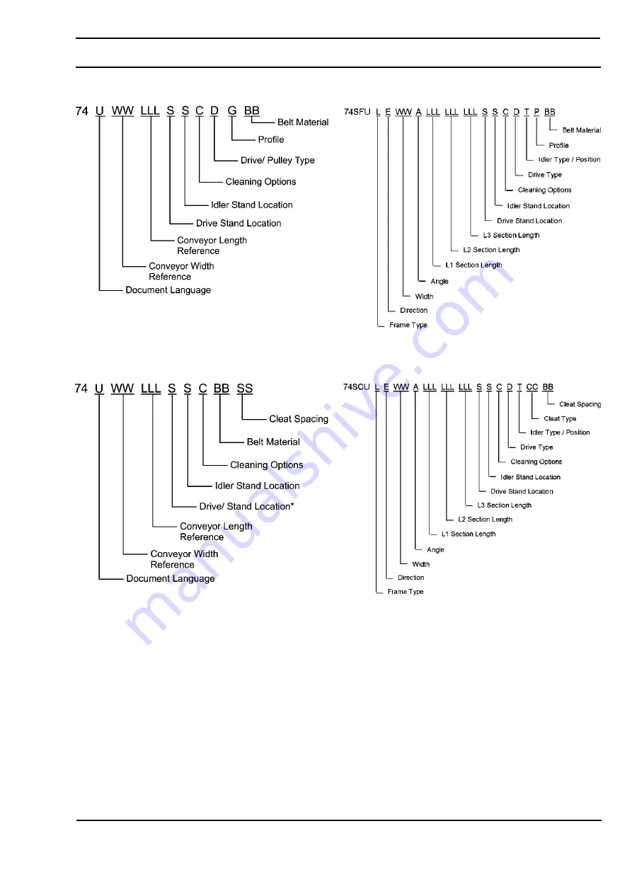
Flat Belt 7400 Series Conveyor
Cleated Belt 7400 Series Conveyor
Flat Belt 7400 Series LPZ Conveyor
Cleated Belt 7400 Series LPZ Conveyor
Page 1: ...ORP INSIDE THE USA OUTSIDE THE USA P O Box 20 975 Cottonwood Ave TEL 1 800 397 8664 TEL 262 367 7600 Hartland WI 53029 0020 USA FAX 1 800 369 2440 FAX 262 367 5827 851 638 Rev E 7400 Series CE End Drive Conveyors Installation Maintenance and Parts Manual Flat Belt Conveyor Cleated Belt Conveyor ...
Page 2: ...5 Idler Tail and Tip Up Tail 25 Drive Tail 25 Bearing Replacement 27 LPZ Knuckles 27 Wearstrips and Belt Returns 27 Service Parts 28 Drive End Components 28 Tension End Components 30 Tip Up Tension End 31 Nose Bar Tension End 32 Nose Bar Tip Up Tension End 33 Conveyor Frame and Extension 34 Upper Knuckle for 5 15 35 Upper Knuckle for 30 60 36 Lower Knuckle for 5 15 37 Lower Knuckle for 30 60 38 76...
Page 3: ...EIGHT OR ANGLE ADJUSTMENT SCREWS Loosening stand height or angle adjustment screws may cause conveyor sections to drop down causing serious injury WARNING SEVERE HAZARD LOCK OUT POWER before removing guards or performing maintenance Exposed moving parts can cause serious injury WARNING BURN HAZARD DO NOT TOUCH the motor while operating or shortly after being turned off Motors may be HOT and can ca...
Page 4: ...nd Drive Conveyors Product Description Refer to Figure 1 for typical conveyor components Figure 1 Typical Components 1 Conveyor 2 Gearmotor 3 Belt Flat Belt Shown 4 Return 5 Support Stands 6 Motor Controller 7 Drive End 8 Tension End 3 2 7 5 6 4 1 8 ...
Page 5: ...Dorner Mfg Corp 7400 Series CE End Drive Conveyors Specifications Specifications Flat Belt 7400 Series Conveyor Cleated Belt 7400 Series Conveyor Flat Belt 7400 Series LPZ Conveyor Cleated Belt 7400 Series LPZ Conveyor ...
Page 6: ...2 Belt Travel 305 mm 12 per revolution of pulley Maximum Belt Speed 71 m minute 233 ft minute Belt Take up 51 mm 2 Conveyor Length Reference LLL 036 999 in 001 increments Conveyor Length 36 914 mm 999 25 4 m in 1 25 mm increments LPZ Section Lengths LLL 024 252 in 001 increments LPZ Section Length 24 610 mm 252 6401 mm in 1 25 mm increments Total LPZ Conveyor Length L1 L2 L3 Maximum 11 6 m 38 long...
Page 7: ... Install the belt Refer to Belt Installation on page 15 7 Attach the belt returns Refer to Belt Return Installation on page 16 8 Attach any guides accessories Refer to the Service Parts section starting on page 28 Conveyors Longer than 3048 mm Typical Connection Components Figure 4 Figure 4 1 Locate the section number sequence etched on each section of frame Figure 5 item 1 Figure 5 2 Position the...
Page 8: ...knuckle Figure 7 item 1 to frame Figure 7 item 2 with hex rods Figure 7 item 3 and bolts Figure 7 item 4 Figure 7 2 Install wear strips Figure 7 item 5 3 Attach lower knuckle Figure 8 item 1 to frame Figure 8 item 2 with hex rods Figure 8 item 3 and bolts Figure 8 item 4 Figure 8 4 Install wear strips Figure 8 item 5 Belt 1 Slide belt Figure 9 item 1 over knuckles on top of the wear strips Figure ...
Page 9: ...es and secure with pull pin Figure 10 item 3 3 Slide guides Figure 11 item 1 onto lower knuckle frame and secure with pull pins Figure 11 item 2 Figure 11 All Conveyors Stand Installation Typical Stand Components Figure 12 Figure 12 1 Position the stands on a flat level surface 2 Attach the stands to the frame Figure 13 Figure 13 1 2 3 1 2 1 Conveyor frame 2 Stand 3 M10 1 5 x 12 mm hex head cap sc...
Page 10: ...o the take up blocks Figure 15 item 2 Figure 15 2 Install the drive package if applicable Refer to the 7400 Series Drive Package Installation Maintenance and Parts Manual 3 Insert the pull pins Figure 16 item 1 Figure 16 Idler Tail Typical Idler Tail Components Figure 17 Figure 17 1 Drive tail assembly 2 Pull pin x2 3 Conveyor frame 3 2 1 2 1 3 1 2 1 Idler tail assembly 2 Pull pin x2 3 Conveyor fr...
Page 11: ...gh the designated slots in the frame Figure 20 2 Attach the key stops Figure 21 item 1 to the tip up shaft Figure 21 item 2 The rounded end of the key stop should be facing the tail Figure 21 3 Slide the bearing shafts Figure 22 item 1 into the holes in the tip up shaft Figure 22 item 2 Figure 22 NOTE Do not insert the pull pins on the tension end of the conveyor until the belt has been installed ...
Page 12: ...Ensure that the nose bar pucks Figure 25 item 1 are in line with the conveyor frame Figure 25 item 2 Figure 25 Nose Bar Tip Up Tail Typical Nose Bar Tip Up Tail Components Figure 26 Figure 26 NOTE Do not insert the pull pins on the tension end of the conveyor until the belt has been installed 1 Nose bar idler tail assembly 2 Pull pin x2 3 Conveyor frame 1 2 3 1 2 3 2 1 3 NOTE Do not insert the pul...
Page 13: ...should face the tail Figure 28 3 Attach the nose bar idler shaft hands Figure 29 item 1 to the tip up shaft Figure 29 item 2 Figure 29 4 Attach the nose bar transfer post Figure 30 item 1 to the nose bar idler shaft hands Figure 30 item 2 Figure 30 5 Ensure that the nose bar pucks Figure 31 item 1 are in line with the conveyor frame Figure 31 item 2 Figure 31 1 1 2 1 2 NOTE Do not insert the pull ...
Page 14: ...33 item 1 Make sure the hooked ends of the lifter bars are facing down when resting against the frame 3 Attach the lifter handle Figure 33 item 3 to the belt lift pivot rod Wear Strip Installation Typical Wear Strip Components Figure 34 Figure 34 1 Position the wear strips Figure 35 item 1 on the frame Figure 35 2 Make sure the wear strips are situated securely in the frame slots Figure 35 item 2 ...
Page 15: ...rocket teeth have engaged the belt 3 Bring the ends of the belt together Figure 38 Figure 38 4 Insert the belt rod Figure 39 item 1 Figure 39 5 Push the belt rod in as far as possible 6 Lightly tap the head of the rod with a hammer until it snaps into position 7 Extend the tension end to remove excess slack in the belt Figure 40 Figure 40 8 Insert the pull pins Figure 41 item 1 on the tension end ...
Page 16: ...haft Figure 44 item 1 up and through the large slot Figure 44 item 2 in the frame picture shown without the belt or wear strips Figure 44 3 Push up on the return shaft Figure 44 item 1 and slide the notched end of the shaft through the small slot on the opposite side of the frame 4 Check belt sag by measuring from the top of the return Figure 45 Belt sag should not exceed 102 mm Follow steps 7 9 i...
Page 17: ...Figure 46 item 2 to the frame Figure 46 2 Remove the pull pin Figure 47 item 1 on the tension end of the conveyor to release belt tension Figure 47 3 Lift up on the belt Figure 48 Figure 48 Conveyors with Tip Up Tails and Lifters 1 Remove the guides if applicable by removing the pull pins Figure 46 item 1 that connect the guide Figure 46 item 2 to the frame 2 Use the lifter handle Figure 49 item 1...
Page 18: ...e 14 Refer to Belt Return Installation on page 16 Maintaining the Conveyor Belt Troubleshooting Inspect conveyor belt for Surface cuts or wear Skipping Damage to belt links or rods surface cuts and or wear indicate Sharp or heavy parts impacting belt Jammed parts Accumulated dirt Foreign material inside the conveyor Improperly positioned accessories Skipping indicates Excessive load on belt Worn s...
Page 19: ...elts on page 21 Standard Belts Replacing a Section of Belt 1 Remove the pull pins Figure 53 item 1 on the tension end of the conveyor to release tension on the belt Figure 53 2 Secure the retaining head side of the belt Use the belt removal tool Figure 54 item 1 for 1 pitch belts For all other belts position the section of belt so that it is braced by the flanged puck Figure 54 item 2 Figure 54 WA...
Page 20: ...slide it out of the frame 3 Follow steps 1 3 in Standard Belts Replacing a Section of Belt on page 19 4 Remove the belt 5 Replace the damaged or worn belt Refer to Belt Installation on page 15 and Belt Return Installation on page 16 Specialty Intralox 1100 Series Belts Replacing a Section of Belt 1 Place the edge of a flat head screwdriver between the the two belt links and turn clockwise Figure 5...
Page 21: ...ide 2 Use a flat head screwdriver to raise the end of the belt rod above the retention lip Figure 60 Figure 60 3 Remove the bet rod by gripping the end with a set of pliers and pulling Figure 61 Figure 61 4 Remove the belt rods on both sides of the section of belt being replaced 5 Replace the old section with a new section of belt Replacing the Entire Belt 1 Remove the belt returns by pushing up o...
Page 22: ...age 19 Sprocket and Puck Removal 1 Remove the conveyor belt to access the sprockets pucks Refer to Conveyor Belt Replacement on page 19 2 Remove the desired sprocket puck by following these instructions A Drive Sprocket Removal B Idler Puck Removal A Drive Sprocket Removal WARNING SEVERE HAZARD LOCK OUT POWER before removing guards or performing maintenance Exposed moving parts can cause serious i...
Page 23: ...move the upper gearhead mounting bar Figure 66 item 4 from the motor mounting bracket Figure 66 item 2 Figure 66 4 Slide the gearmotor Figure 67 item 1 off of the drive spindle Figure 67 item 2 Figure 67 5 Remove the drive spindle key Figure 68 item 1 from the drive spindle keyway Figure 68 item 2 Figure 68 6 Remove the pull pin Figure 69 item 1 Figure 69 7 Slide the drive tail assembly out of the...
Page 24: ...ut of the take up blocks Figure 71 item 2 Figure 71 3 Remove the bearing cover Figure 72 item 1 Figure 72 4 Use a hex wrench Figure 73 item 1 to loosen the bearing shaft assembly fasteners Figure 73 item 2 Figure 73 5 Slide the bearing shaft assembly Figure 74 item 1 off the idler shaft Figure 74 item 2 Figure 74 6 Remove the guard bar Figure 75 item 1 Figure 75 7 Remove the pucks Figure 75 item 2...
Page 25: ...shaft Figure 76 item 3 Make sure to center the idler puck Figure 76 3 Attach the flanged pucks Figure 77 item 2 and bearing shaft assemblies to the idler shaft 4 Attach the guard bar Figure 77 item 1 Figure 77 5 Use a hex wrench Figure 78 item 1 to tighten the bearing shaft fasteners Figure 78 item 2 to 6 N m Check after 24 hours of conveyor use Figure 78 6 Attach the bearing covers Drive Tail 1 A...
Page 26: ...et alignment bar Figure 81 5 Slide the second flanged puck Figure 82 item 1 and the retaining ring Figure 82 item 2 onto the drive spindle Figure 82 6 Tighten the retainer ring fastener using a hex wrench Figure 82 item 3 7 Slide the second bearing shaft assembly or the motor mount bracket Figure 83 item 1 onto the longer end of the drive spindle Figure 83 item 2 Figure 83 8 Attach the guard bar F...
Page 27: ...n or damaged bearing Figure 87 Figure 87 5 Replace the bearing LPZ Knuckles Wearstrips and Belt Returns Replace the wearstrips and belt returns if they become worn For wearstrip and belt return installation instructions For wearstrips replace as needed making sure wear strips are situated securely in the frame slots For belt returns Refer to Belt Return Installation on page 16 NOTE When inserting ...
Page 28: ...3WW Flanged Puck Drive Tail for Standard Belt 5071WW Flanged Puck Drive Tail for Specialty Intralox Belt 4 807 1444 Sprocket for Standard 1 00 Pitch Belt 807 1446 Sprocket for Specialty Intralox 60 Pitch Belt 807 1445 Sprocket for Specialty Intralox 1 00 Pitch Belt 5 5295WW Drive Spindle for Standard Belt 5294WW Drive Spindle for Specialty Intralox Belt 6 5085WW Sprocket Alignment Bar for Standard...
Page 29: ...ncludes Items 1 3 4 and 11 74DC11 WW Drive Spindle Kit when Conveyor is ordered without a Dorner Gearmotor Mounting Package for Specialty Intralox 60 Pitch Belt Includes Items 1 3 4 and 11 74DC16 WW Drive Spindle Kit when Conveyor is ordered without a Dorner Gearmotor Mounting Package for Specialty Intralox 1 00 Pitch Belt Includes Items 1 3 4 and 11 WW Conveyor width ref 06 60 in 02 increments Wh...
Page 30: ...W Bent Retaining Bar for Standard Belt for 8 60 wide conveyors only 5073WW Bent Retaining Bar for Specialty Intralox Belt for 8 60 wide conveyors only 7 5009WW Guard Bar 8 807 1469 Pull Pin 9 802 162 Bearing 10 74I WW Idler Spindle Kit for Standard Belt Includes Items 1 3 4 and 9 74IS WW Idler Spindle Kit for Specialty Intralox Belt Includes Items 1 3 4 and 9 11 74IT WW Idler Tail Kit for Standard...
Page 31: ...for Standard Belt for 8 60 wide conveyors only 5073WW Bent Retaining Bar for Specialty Intralox Belt for 8 60 wide conveyors only 7 5009WW Guard Bar 8 500675 Key Stop 9 5005WW Tip Up Shaft Assembly 10 807 1469 Pull Pin 11 802 162 Bearing 12 74I WW Idler Spindle Kit for Standard Belt Includes Items 1 3 4 and 11 74IS WW Idler Spindle Kit for Specialty Intralox Belt Includes Items 1 3 4 and 11 13 74I...
Page 32: ... Idler Shaft Left Hand 6 500488 Nose Bar Idler Shaft Right Hand 7 807 1469 Pull Pin 8 74NB5 WW 5 Nose Bar Kit Includes Items 1 through 3 74NB1 WW 1 Nose Bar Kit Includes Items 1 through 3 9 74NBT5 WW 5 Nose Bar Tail Kit for Standard Belt Includes Items 1 through 6 74NBT1 WW 1 Nose Bar Tail Kit for Standard Belt Includes Items 1 through 6 74NBT5S WW 5 Nose Bar Tail Kit for Specialty Intralox Belt I...
Page 33: ...t Hand 6 500488 Nose Bar Idler Shaft Right Hand 7 500675 Key Stop 8 5005WW Tip Up Shaft Assembly 9 807 1469 Pull Pin 10 74NB5 WW 5 Nose Bar Kit Includes Items 1 through 3 74NB1 WW 1 Nose Bar Kit Includes Items 1 through 3 11 74NBT5 WW 5 Nose Bar Tail Kit for Standard Belt Includes Items 1 through 6 74NBT1 WW 1 Nose Bar Tail Kit for Standard Belt Includes Items 1 through 6 74NBT5S WW 5 Nose Bar Tai...
Page 34: ...4 14 3 6 9 12 15 18 21 24 16 4 8 12 16 20 24 28 32 18 4 8 12 16 20 24 28 32 20 5 10 15 20 25 30 35 40 22 5 10 15 20 25 30 35 40 24 5 10 15 20 25 30 35 40 Conveyor Width WW 26 6 12 18 24 30 36 42 48 28 6 12 18 24 30 36 42 48 30 6 12 18 24 30 36 42 48 32 7 14 21 28 35 42 49 56 34 7 14 21 28 35 42 49 56 36 8 16 24 32 40 48 56 64 38 8 16 24 32 40 48 56 64 40 8 16 24 32 40 48 56 64 42 9 18 27 36 45 54 ...
Page 35: ... Hand 18 24 wide 501883 AA 76 mm Hold Down Guide for 5 15 Knuckle Right Hand 6 16 wide 501684 AA 38 mm Hold Down Guide for 5 15 Knuckle Right Hand 18 24 wide 4 501699 AA 38 mm Hold Down Guide for 5 15 Knuckle Left Hand 6 16 wide 501687 AA 38 mm Hold Down Guide for 5 15 Knuckle Left Hand 18 24 wide 501698 AA 76 mm Hold Down Guide for 5 15 Knuckle Left Hand 6 16 wide 501686 AA 76 mm Hold Down Guide ...
Page 36: ...228WW Frame Assembly for 45 Knuckle 5229WW Frame Assembly for 60 Knuckle 2 501693 AA Wear Strips for 30 60 Knuckle 3 501697 AA 38 mm Hold Down Guide for 30 60 Knuckle 501879 AA 76 mm Hold Down Guide for 30 60 Knuckle 4 807 1553 Pull Pin 5 501683 Return Guide 6 74UKH WW AA Upper Knuckle Kit Includes items 2 and 5 WW Conveyor width ref 06 24 in 02 increments AA Angle 30 45 or 60 Item Part Number Des...
Page 37: ...for 15 Knuckle 2 501694 AA Wear Strips for 5 15 Knuckle 3 501692 AA 38 mm Hold Down Guide for 5 15 Knuckle 6 16 wide 501974 AA 38 mm Hold Down Guide for 5 15 Knuckle 18 24 wide 501878 AA 76 mm Hold Down Guide for 5 15 Knuckle 6 16 wide 501973 AA 76 mm Hold Down Guide for 5 15 Knuckle 18 24 wide 4 807 1553 Pull Pin 5 74LKL WW AA Lower Knuckle Kit Includes item 2 WW Conveyor width ref 06 24 in 02 in...
Page 38: ...30 Knuckle 5222WW Frame Assembly for 45 Knuckle 5223WW Frame Assembly for 60 Knuckle 2 501691 AA Wear Strips for 30 60 Knuckle 3 501692 AA 38 mm Hold Down Guide for 30 60 Knuckle 501878 AA 76 mm Hold Down Guide for 30 60 Knuckle 4 807 1553 Pull Pin 5 74LKH WW AA Lower Knuckle Kit Includes item 2 WW Conveyor width ref 06 24 in 02 increments AA Angle 30 45 or 60 Item Part Number Description ...
Page 39: ...0 Conveyors For 21 30 Conveyors Number of guiding sections increases every 10 Item Part Number Description 1 503501 LLLLL Right Hand High Side Guide 2 503601 LLLLL Left Hand High Side Guide 3 807 1553 Pull Pin 4 503401 LLLLL Square End High Side Guide LLLLL Guide Length in inches with 2 decimal places Example Guide Length 95 25 LLLLL 09525 Item Part Number Description ...
Page 40: ...ated Right Hand Guide 6 16 wide conveyors 502402 LLLLL 25 mm Cleated Right Hand Guide 18 24 wide conveyors 2 502501 LLLLL 25 mm Cleated Left Hand Guide 6 16 wide conveyors 502502 LLLLL 25 mm Cleated Left Hand Guide 18 24 wide conveyors 3 807 1553 Pull Pin 4 502301 LLLLL 25 mm Cleated Guide Square End 6 16 wide conveyors 502302 LLLLL 25 mm Cleated Guide Square End 18 24 wide conveyors LLLLL Guide L...
Page 41: ...t Hand Guide 6 16 wide conveyors 502702 LLLLL 76 mm Cleated Right Hand Guide 18 24 wide conveyors 2 502801 LLLLL 76 mm Cleated Left Hand Guide 6 16 wide conveyors 502802 LLLLL 76 mm Cleated Left Hand Guide 18 24 wide conveyors 3 807 1553 Pull Pin 4 502601 LLLLL 76 mm Cleated Guide Square End 6 16 wide conveyors 502602 LLLLL 76 mm Cleated Guide Square End 18 24 wide conveyors LLLLL Guide Length in ...
Page 42: ...er Description 1 5032WW Return Shaft 2 500075 Chain Return Shoe 3 74R WW Chain Support Kit Includes Item 2 WW Conveyor width ref 06 60 in 02 increments Item Part Number Description 2 1 3 Chain Support Kit Item Part Number Description 1 500196 Cleated Return Shaft 2 500075 Chain Return Shoe 3 74CR Chain Support Kit Includes Item 2 Item Part Number Description ...
Page 43: ...r WW Conveyor width ref 06 60 in 02 increments Belt Removal Tool Item Part Number Description 1 74BB WW Flat Belt Chain Repair Kit Includes 1 ft 305 mm of flat belt chain and assembly pins BB Chain Reference Number WW Conveyor width ref 06 60 in 02 increments Flat Belt Chain Kit Item Part Number Description 1 74BB WW SS Cleated Belt Chain Repair Kit Includes 1 cleat centered on a cleat spacing len...
Page 44: ...from each end frame cutout cleaning option side drive with standard pulleys on each end low side profiles and MA belt material Cleated Belt Conveyor Refer to the model number on the conveyor frame Figure 88 From the model number determine conveyor width WW length LLL drive stand location S idler stand location S cleaning options C cleated belt material BB and cleat spacing SS Example 74U12072CC1NA...
Page 45: ...851 638 Rev E 45 Dorner Mfg Corp 7400 Series CE End Drive Conveyors Notes Notes ...
Page 46: ... and accessories 30 Sanitary stand supports non returnable items Parts Standard stock parts 30 MPB cleated and specialty belts non returnable items Returns will not be accepted after 60 days from original invoice date The return charge covers inspection cleaning disassembly disposal and reissuing of components to inventory If a replacement is needed prior to evaluation of returned item a purchase ...