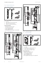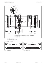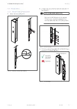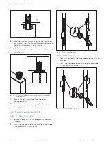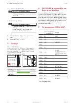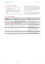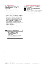
4.7 Mounting active leaf
TIPS AND RECOMMENDATIONS
• Observe the applicable documents for the
SVA lock.
4.8 Mounting fittings
TIPS AND RECOMMENDATIONS
• Observe the applicable documents for the
fittings.
• Other manufacturers’ fittings must
correspond to the intended use.
1.
Mount the fittings (door handle, panic bar or
knob).
2.
Check the fittings’ function.
5 Displays
5.1 LED display
With the SVI 2000/2000F, colored light signals in
the area around the latch holder indicate general
operational readiness. In addition, the LED display
shows the error messages
(“9 Error messages” on page 23).
Fig. 58
SVI 2000
SVI 4000
SVI 5000
SVI 2000F
LED displays in the latch holder
LED display
Color
Duration
Ready for
operation
2000 ms
6
SVA 2000F integrated Power
Reserve module test
The internal Power Reserve module is tested 5
minutes after the power is turned on and then every
48 hours. If the test completes with an error, the
corresponding flashing code appears once according
to the error messages (see chapter 9). The test is then
performed a second time after a further 5 minutes.
If this test is also negative, the flashing code is
permanently displayed.
7 Pin assignment SVI 2000(F)
SVP-A 1100/2100
cable colors
Wiring
PIN 1
bk
GND
PIN 2
rd
-
PIN 3
wh
+24V DC
PIN 4
-
PIN 5
bn
-
PIN 6
vio
Locked,
output switches to
GND, 30 mA at max.
30 V DC
PIN 7
rd/bu
-
PIN 8
bu
PIN 9
gn
-
PIN 10
pk/gy
Bolt contact *
PIN 11
ye
Bolt contact *
PIN 12
-
PIN 13
gy
RS485 N
PIN 14
pk
RS485 P
* only for special items
22
SVI Lock
2019-12
dormakaba Mounting instructions
Displays
WN 059741 45532

