For 480i Lock Programming with M-Unit
LOCK PROGRAMMING
MAINTENANCE WHEN REQUIRED
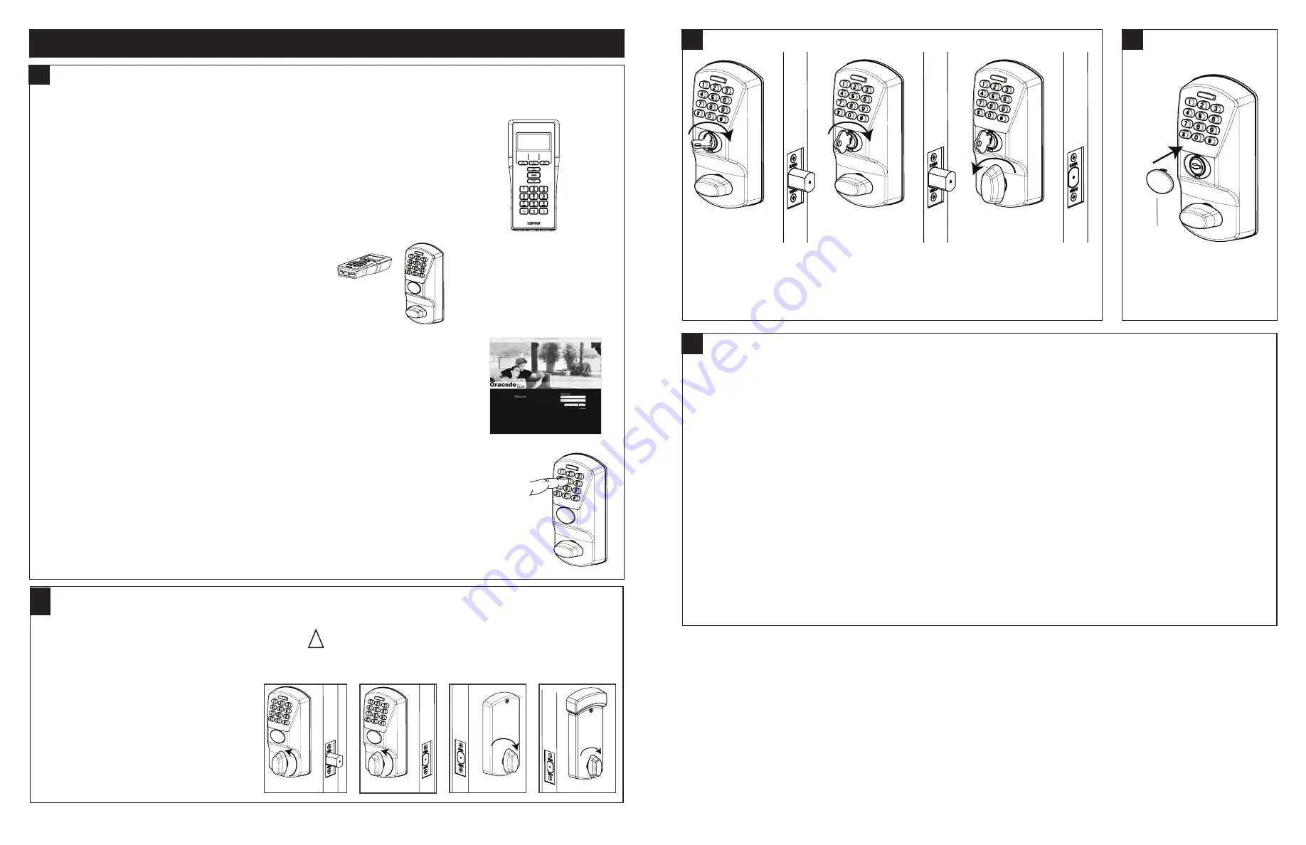
TESTING THE OPERATION OF THE LOCK
TESTING THE MECHANICAL OVERRIDE (with door open)
COVER THE KEY HOLE
Perform all the following with the door open.
1. Project the dead bolt if it is not projected.
2. Turn outside thumbturn, the deadbolt
must not retract. See Fig. 1.
3. Enter code.
4. Retract dead bolt from outside.
See Fig. 2.
5. Wait 15 seconds.
6. Rotate outside thumbturn to
project the dead bolt.
7. Rotate inside thumbturn to retract
the dead bolt. See Fig. 3 & Fig. 4.
1. Project the dead bolt from outside or inside.
2. Insert key and rotate it clockwise until it stops. See Fig. 4 & Fig. 5.
3. Rotate outside thumbturn to retract the dead bolt. See Fig. 6.
NOTE:
The key override always rotates clockwise.
IMPORTANT:
If your lock is already pre-programmed, you can go directly to section 3 below. Otherwise, follow the
instructions in sections 1 and 2 below to program the lock.
1. MAINTENANCE UNIT
To program the lock, you will need a Maintenance Unit running the Oracode application and
the correct door configuration. You will need to login on the Kaba e-code Web Site (www.
kaba-ecode.com) with a valid Username and Password in order to create the door and
download it to the Maintenance Unit. If necessary, contact the Kaba Technical Support
Hotline (1-888-217-5654 US & Canada), (1-514-340-9025 International) or contact your
Oracode representative for assistance.
1. TIME PROGRAMMING
The time is set automatically in the lock when the lock is programmed. The Oracode lock time should then be reset
every year with the Maintenance Unit to ensure accurate time.
The lock has an internal battery back-up that keeps the internal time accurate for a minimum of four weeks when
the lock's batteries are disconnected. If this period is surpassed and the lock time is lost, the green LED will blink
twice after a valid code is entered, and the red LED will blink twice after a code is refused. This indicates that the
time must be reset with the Maintenance Unit.
2. RESET TO FACTORY DEFAULT
NOTE: You will need to reprogram the lock with a Maintenance Unit after you perform a Reset to Factory Default.
Perform the following steps to erase a lock's configuration and restore the default factory settings.
1. Remove the inside cover and remove the batteries.
2. After 1 minute, re-install the batteries. The green LED should blink quickly for 15 seconds.
3. Press #,#,# while the green LED is blinking. The green and red LED should blink one after the other for
15 seconds.
4. Press 1, 2, 3, 4, 5, 6 while the red and green LEDs are blinking. You will hear a longer beep and see a longer green
LED flash when the code is accepted and the default factory setting are restored. If a red LED flashes and a
low-pitch beep is heard, this indicates that the code is refused.
2. LOCK PROGRAMMING
Program the lock using the Oracode Maintenance Unit.
3. CODE GENERATION
Generate a valid code for this door on the www.kabaecodewireless.com website. You will
need to login with a valid Username and Password in order to generate codes.
4. CODE ENTRY AND ACCESS
Enter the valid code on the lock keypad. A short beep can be heard and the green LED flashes for
each key pressed. You will hear a longer beep and see a longer green LED flash when the code is
accepted. The outside turn knob is then engaged for several seconds (5 to 15seconds, depending on
the configuration). If a red LED flashes and a low-pitch beep is heard when the code is entered, this
indicates that the code is refused.
IMPORTANT:
Make sure that the door is programmed properly and a valid code is accepted. If a valid
code is not accepted, contact the Kaba Technical Support Hotline.
Fig. 1
Fig. 4
Groove
facing down
Fig. 2
Fig. 3
Fig. 4
Fig. 5
Fig. 6
!
11
12
13
15
14
PK3700 2018-06-29
Page 3 of 4


