SSRLS-3 / SSRLU-3
Installation Instructions
INS SSRLS_SSRLU-3 v10.2.vsd Created: 5-14-2018 Revised: 5-14-2018
Page 6
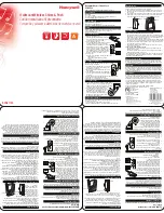
OUT-SWING:
ALUMINUM ANGLE INSTALLATION
1) Close the door first! Line up the edge of the aluminum angle with
edge of the frame and strike opening with main bolt as shown.
Make sure Bolts are not rubbing and door can open easily.
2) Fasten the aluminum angle to the frame with #14 hex head self drilling
screws.
3) Keeping the door pulled against the door stop, extend the bolts as much
as possible. Trace the outline of the top and bottom bolts & .
4) Open the door and mark the centers of the top and bottom holes .
Center punch the point to be drilled. Drill a 1/8" pilot hole first and then
enlarge to ¾
”
and remove all burrs.
The dead bolt dia. Is 5/8" . A ¾
”
hole, if drilled on center, should be
sufficient. If you feel any rubbing, check to see which part of the bolt
is rubbing in the hole and grind or enlarge that side of the hole.
5) Mount strike to the aluminum angle with ¼ - 20 flat head Phillips
screws and ¼-20 K-Lock nuts. So, that roller faces you and is flush
with aluminum angle as shown in . Adjust so that main bolt operates
smoothly and tighten the K-Lock nuts completely.
6) Check lock for the smooth operation.
A
B
C
D
A
B
C
44"
(suggested)
Select a height
which is
comfortable
for users
Select a height
which is
comfortable
for users
44"
(suggested)
Select a height
which is
comfortable
for users
OUT-SWING MODEL
Upper Module
Lower
Module
C
ha
nn
el
Al
um
in
iu
m
A
ng
le
44"
(suggested)
Select a height
which is
comfortable
for users
OUT-SWING MODEL
Upper Module
Lower
Module
C
ha
nn
el
Al
um
in
iu
m
A
ng
le
Aluminum
Angle
D
Top & Bottom
Bolt Hole
C
Strike
Opening
¼ - 20
K-Lock Nut
¼ - 20
Flat Head
Phillips
Screw
Aluminium
Angle bracket
E
E
Inswing:
Frame
Stop
Frame
Face
9/16"
1"
9/16"
1-3/4"
s
id
e
v
ie
w
o
f s
tr
ik
e
p
la
te
side
view of
strike
box
2 each 8 x 5/8" Hex Washer
Slotted Head Sheet Metal
Screw - Chrome Zinc
2 each 14 x 1-1/2" Hex
Washer Head Self-Drilling
Screw - Black
Suggest drilling 1/8"
pilot hole for large
Screws
1-1/8"
Cut rectangle
1"W x 1-3/4"H
into frame stop
for Strike Box.
3/ 4"
D
IS
TA
N
C
E
G
U
ID
E
bo
x
fro
m
S
te
p
1
Suggest drilling 1/8"
pilot hole for large
Screws
1) Extend the bolts and draw center
line for the bolt.
2) Using a chisel, chop out the rectangle
1" x 1-3/4".Be sure the box can be
placed at least ¾
”
deep into stop.
3) File the edges smooth.
4)
Install the Main Deadbolt Strike
Place the box strike into the hole.
Mark and drill
1/8”
pilot holes at the
oval inner holes. Fasten the strike
loosely with the 2 large self-drilling
hex head screws. Adjust sideways
as needed so the bolt moves freely
before tightening the screws
completely.
5) After making the final strike position adjustment, insert the 2 small slot-hex head
sheet metal screws into round outer holes to secure.
A
B
C
D
E
B
E
Main Lock
Body
Bolt
Extended