(P/N) 3047.025 Rev D 06/18 • © copyright 2005 - 2018
dormakaba USA Inc.
Page 2 of 4
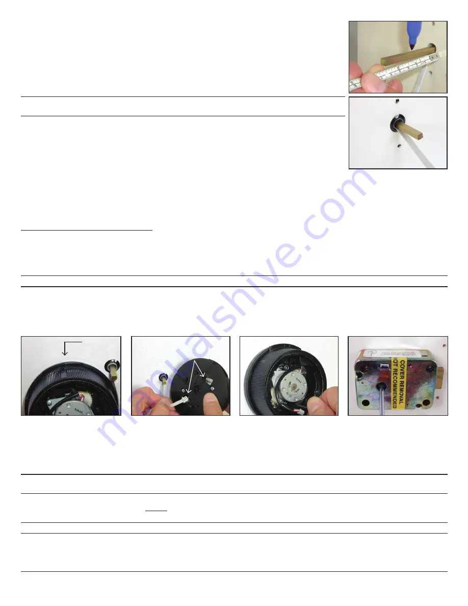
4. Mark the tube flush to the outside of the container door (to within 1/16” or 1.6mm).
5. Remove lock case assembly from door and cut the tube just inside your mark.
6. Plug one end of the ribbon cable into the connector on the bottom of the lock case. (Figure 3)
7. Lay the ribbon cable in the cable routing path on the lock case and tape the cable to the outside
of the tube with the insulator tape provided. (Figure 3)
8. Hold the lock case assembly and carefully guide the loose end of the ribbon cable and the tube
through the spindle hole so that they are accessible outside of the container door.
9. Mount the lock case assembly to the inside of the container door using the four 1/4-20 (or M6-1)
lock case mounting screws. (Torque 25-30 lbs., 2.8-3.4 N-M)
NOTE:
The lock case assembly can be mounted in all orientations for all mounting locations. It is
recommended that you use Loctite
®
262 (Red) on the lock case mounting screws.
10. Insert the end of the spindle with the screw hole into the lock case assembly until the spindle is
properly seated. The grooved side of the spindle should be oriented so that the grooves in the
spindle align with the grooves in the drive cam. Turn the spindle to extend the bolt and ensure
that the grooves are facing toward the bolt.
11. Mark the spindle shaft 3/8” (9.5mm) from the outside of the container door (plus or minus 1/16”
or 1.6mm allowed). (Figure 4)
12. Remove the spindle from the lock case to prevent damage to the cable while cutting.
13. Cut the spindle on the mark and deburr.
14. Re-insert the spindle. Refer to Step 10 for proper positioning.
15. Insert the second cable shield into the spindle hole from the front of the container with the cable feeding through the center of
it. (Figure 5)
Part II: Install Front Housing Assembly
1. Hold the dial assembly in the upright position. (Red area on the dial assembly should be at top of dial). The lip on the dial should
be positioned to cover the red area.This is referred to as the “HOME” position. (See correct dial position in Figure 6.)
2. Guide the ribbon cable through the appropriate cable receiving hole, based on the orientation of the ribbon cable to the spindle.
(Figure 7).
3. Align the dial assembly with the mounting holes and spindle, and position against the outside of the container door.
CAUTION:
Do not turn the dial at this time as you could damage the cable.
4. While holding the dial assembly in place, attach it to the container door using the two #8-32 dial assembly mounting screws
and the 9/64” Allen wrench. Tighten the screws (Torque 17-20 lbs., 1.9-2.25 N-M) and then ensure that the dial turns smoothly.
(Figure 8)
5. While holding the dial in place, insert the #6-32 spindle mounting screw through the back of the lock case and into the end of
the spindle. (Figure 9) Turn the screw until it is securely attached to the spindle. (Torque 14-16 lbs., 1.6-1.8 N-M)
Figure 4
Figure 5
Figure 6
HOME: Red
portion is not
showing
Cable receiving holes
Figure 7
Figure 8
Figure 9
6. Insert the 4-pin generator cable on the dial assembly into the 4-pin connector on the back of the keypad assembly. The
generator cable will only connect to the keypad assembly in one orientation. (Figure 10)
7. Insert the keyed Picoflex connector on the end of the ribbon cable into the connection header on the keypad. (Figure 11)
8. Position the generator cable and the ribbon cable around the generator in a counter-clockwise direction to ensure that the
cables will not be pinched when you attach the keypad assembly. (Figure 12).
9. Orient the lip of the dial to the HOME position.
CAUTION
Next Step: Once the keypad assembly is snapped into place, it cannot be easily removed without performing an
“uninstall” procedure.
Do not snap the keypad assembly into place when performing the next step.
10. Align the keypad assembly in the upright position and
carefully
insert the two catches on the keypad assembly into the
notches on the dial assembly, but
do not snap the keypad assembly into place
. (Figure 13)
11. Test the operation of the lock before completing the installation of the keypad assembly by verifying the following:
NOTE:
If the keypad is not oriented correctly, you can remove the keypad and adjust the orientation of the dial assembly.


