


- 53 -
LP Engine G430 (3.0L)
Igntion System
Magnetic Flux Path
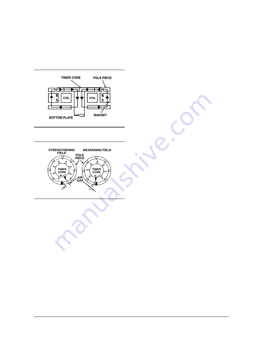
A timer core on the main shaft of the distributor has
external teeth which align with an equal number or
pole piece teeth.
Figure 6-4 Magnetic Flux Path
Figure 6-5 Magnetic Field Strength Variation
The magnetic pickup assembly, by the varying
magnetic field around the pickup coil, produces
electric current in the pickup coil by electromagnet
induction. As the timer core rotates past the pole
piece, the air gap between timer core and pole piece
teeth varies. Since air is not a good path magnetic flux
to travel through, the magnetic field relatively weak
when the teeth are not aligned. the timer core rotates,
the teeth move closer together, the air gap decreases
and the magnetic field increases until the timer core
teeth and pole piece teeth are aligned (figures 6-4 and
6-5).
At this point, the magnetic field is at its strongest. As
the teeth move apart, the air gap increases and the
magnetic field decreases until the teeth begin to move
back together.
Applying the principle of electromagnetic induction
which states that a voltage will be induced in a
conductor whenever a magnetic field is moved so that
its lines of force (flux) cut across a conductor. During
the strengthening and weakening of the magnetic
field, the lines of force cut across the pick-up coil
inducing a voltage in the coil.
The principle of electromagnetic induction also states
that the polarity of the induced voltage depends on
which side of the conductor is striking the magnetic
lines first. This means that the voltage induced by a
strengthening or expanding magnetic field will be of
the opposite polarity of a voltage induced by a
weakening or collapsing magnetic field.
This signal is used to turn on and off the transistors in
the module that controls the current in the primary
circuit. With one exception, which will be covered later,
the pole piece has the same number of teeth as the
engine has cylinders. This gives the correct number of
"firing" pulses per distributor shaft rotation.
We have eliminated the contact points and breaker
cam by using a pulse generator to time the turning on
and off of the primary circuit. In place of the breaker
cam and points, transistors are used to turn the
current on and off. The wear of the rubbing block and
contact points has been eliminated as has the current
limitations of the contact points.
Current Limiting Circuit
In the past, the transistor was made to operate at a
value less than its maximum to protect it from transient
voltage and electrical current extremes. These
extremes are of short duration but of great magnitude
and can be endured by electromechani-cal devices
like switches, motors and contacts with-out permanent
damage. But for electronic devices, even a few
milliseconds (thousandths of a second) exposure to
voltage and current above its maximum capability may
cause failure. By designing the system with enough
resistance so that these extremes are within the
capabilities of the electronic devices used, these
failures were avoided. This is why no available voltage
gain was achieved.
To eliminate this problem, a current limiting circuit was
added to the HEI module to limit primary current to 5.5
amperes rather than using resistance.
This feature allows the electronic device to operate at
their maximum value. Since the HEI circuit current is
not limited by circuit resistance, the resis-tance wire
was eliminated from the system.
131-061
131-060


