background image

SP001945

Main Pump 
Page 6

DISASSEMBLING AND 
REASSEMBLING PROCEDURES
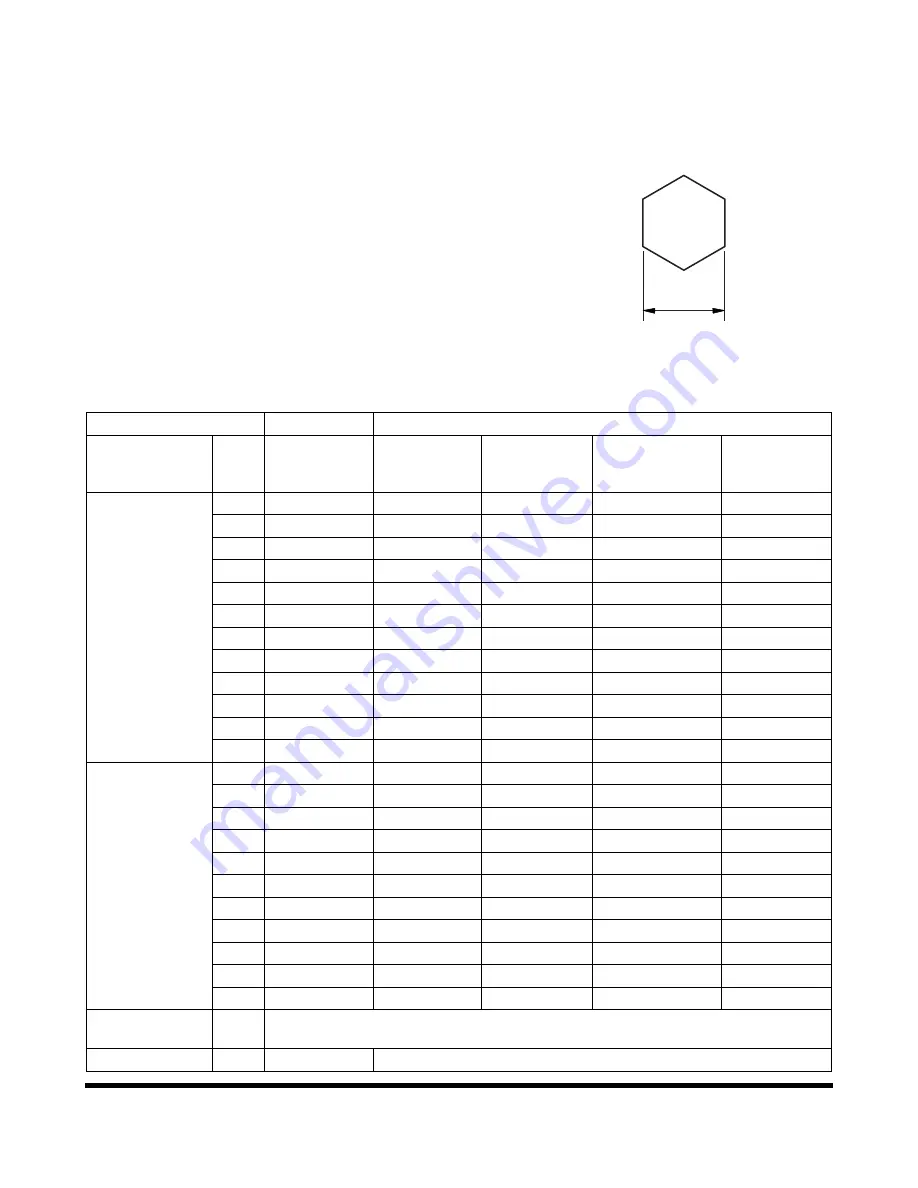
Tool

The tools necessary to disassemble / reassemble K7V pump are
shown in the following list.

The size of the bolts and plugs depend on the pump type.

FG015033

B

Figure 1 

Tool Name & Size

Ο

 Necessary

Part Name

Name

B

K7V63

Hexagon 

socket head 

cap screw

Pressure plug

(PT screw)

ROH plug 

VP plug, UNF plug

(PF screw)

Hexagon 

socket head 

set screw

Allen wrench

2

M4

2.5

M5

3

M6

4

Ο

M5

Rc1/16

M8

5

Ο

M6

Rc1/8

M10

6

Ο

M8

Rc1/4

G1/4

M12, M14

8

Ο

M10

Rc3/8

G3/8

M16, M18

10

Ο

M12

Rc1/2

G1/2

M20

12

M14

14

Ο

M16, M18

Rc3

G3/4

17

Ο

M20, M22

Rc1

G1

19

M24, M27

Double ring 

spanner, socket 

wrench 

Double 
(single) open
end spanner

19

M12

G 1/4

22

3/4-16UNF

24

Ο

M16

27

M18

G 1/2

30

M20

32

1 1/16-12UN

36

G 3/4

41

Ο

G 1

46

M30

50

G1 1/4

55

M36

G1 1/2

Adjustable 

angle wrench

-

Medium size, 1set

Torque wrench

Ο

Capable tightening with the specified torques

Summary of Contents for DX140LCR

Page 1: ...Shop Manual DX140R DX140LCR Serial Number 5001 and Up K1049551BE July 2011 EXCAVATOR ...

Page 2: ......

Page 3: ...nual Shop Manual DX140R DX140LCR EXCAVATOR Serial Number 5001 and Up K1049551BE July 2011 Copyright DOOSAN 2011 DOOSAN and the DOOSAN logo are registered trademarks of DOOSAN Corporation in the United States and various other countries around the world ...

Page 4: ......

Page 5: ...Product Label Instructions Trim Out The Label Along The Lines And Insert Into Pocket On The Binder Spine DX140R DX140LCR Serial Number 5001 and Up Pub No K1049551BE Pub No K1049551BE ...

Page 6: ......

Page 7: ...0813 Upper Structure Cabin SP002282 Counterweight SP001939 Fuel Tank SP001940 Fuel Transfer Pump SP000021 Swing Bearing SP001856 Swing Reduction Gear SP000921 Lower Structure and Chassis Track Assembly SP001941 Engine and Drive Train QSB4 5 Engine SP001671 Drive Coupling Main Pump SP001326 Hydraulics Hydraulic System Troubleshooting Testing and Adjustment SP001942 Accumulator SP000028 Center Joint...

Page 8: ...Valve SP001029 Remote Control Valve Work Lever Joystick SP001646 Travel Control Valve with Damper SP002262 Solenoid Valve Assembly SP001944 Breaker EPPR Valve Opt SP000192 Hydraulic Schematic DX140LCR SP002383 Electrical System Electrical System SP001949 Electrical Schematic DX140LCR SP002271 Attachments Bucket SP000939 ...

Page 9: ...1Safety ...

Page 10: ......

Page 11: ...SP002281 Page 1 Track Excavator Safety SP002281 TRACK EXCAVATOR SAFETYSP002281 Track Excavator Safety Edition 1 ...

Page 12: ...SP002281 Track Excavator Safety Page 2 MEMO ...

Page 13: ...tor of a Excavator 6 General Safety Essentials 9 Location of Safety Labels 10 Summary of Safety Precautions for Lifting in Digging Mode 11 Unauthorized Modifications 12 General Hazard Information 12 Before Starting Engine 22 Machine Operation 26 Maintenance 34 Battery 43 Towing 45 Shipping and Transportation 46 Lifting With Sling 46 ...

Page 14: ...SP002281 Track Excavator Safety Page 4 MEMO ...

Page 15: ...ow all safety recommendations and safe shop practices outlined in the front of this manual or those contained within this section Always use tools and equipment that are in good working order Use lifting and hoisting equipment capable of safely handling load Remember that ultimately safety is your own personal responsibility MODEL SERIAL NUMBER RANGE DX140LCR 5001 and Up ...

Page 16: ...e 1 11 4 Unauthorized Modifications on page 1 12 5 General Hazard Information on page 1 12 6 Before Starting Engine on page 1 22 7 Machine Operation on page 1 26 8 Maintenance on page 1 34 9 Battery on page 1 43 10 Towing on page 1 45 11 Shipping and Transportation on page 1 46 12 Lifting With Sling on page 1 46 DANGER Unsafe use of the excavator could lead to serious injury or death Operating pro...

Page 17: ...must be sure that it is safe for any others In no event should you or others engage in prohibited uses or actions as described in this manual DOOSAN delivers machines that comply with all applicable regulations and standards of the country to which it has been sent If this machine has been purchased in another country or purchased from someone in another country it may lack certain safety devices ...

Page 18: ...in this manual are used you must be sure that you and others can do such procedures and actions safely and without damaging the machine If you are unsure about the safety of any procedures contact a DOOSAN distributor CAUTION This word is used on safety messages and safety labels and indicates potential of a hazardous situation that if not avoided could result in minor or moderate injury It may al...

Page 19: ...city ratings that are printed at the end of this safety section are based on the machine being level on a firm supporting surface with hooks and slings attached in approved configuration Loads must be balanced and supported evenly Use tag lines to keep the load steady if wind conditions and large surface area are a problem Work crew hand signals individual tasks and safe procedures should all be u...

Page 20: ... Safety Page 10 LOCATION OF SAFETY LABELS Location of safety labels decals can vary from unit to unit Refer to appropriate Operation and Maintenance Manual and parts manual for your unit Always replace damaged or faded decals ...

Page 21: ...ifting work DANGER Unsafe use of the excavator while making rated lifts could cause serious potentially fatal injuries or extensive damage to the machine or nearby property Do not let anyone operate the machine unless they ve been properly trained and understand the information in the Operation and Maintenance Manual WARNING NEVER wrap a tag line around your hands or body NEVER rely on tag lines o...

Page 22: ... feeling well if you are taking medication that makes you feel sleepy if you have been drinking or if you are suffering from emotional problems These problems will interfere with your sense of judgment in emergencies and may cause accidents When working with another operator or with a person on work site traffic duty be sure that all personnel know the nature of the work and understand all hand si...

Page 23: ...nsure safety do not use the radio or music headphones when operating the machine There is a danger that this may lead to a serious accident When operating the machine do not put your hands or head out of the window When standing up from the operator s seat always place safety lock lever securely in the LOCK position If you accidentally touch the work equipment levers when they are not locked the m...

Page 24: ...procedures and cabin conditions as described in ISO 6396 NOTE The guaranteed sound power level emitted by the machinery for this machine is given in the operation manual Measurement is obtained on a dynamic machine with the procedures as described in 2000 14 EC Vibration Level Information Hands Arms The weighted root mean square acceleration to which the hands arms are subjected is less than 2 5 m...

Page 25: ...re brakes steering linkages etc 4 Steer brake accelerate shift gears move the attachments and load the attachments smoothly 5 Adjust the machine speed and travel path to reduce the vibration level Slow down if it is necessary when traveling through rough terrain When driving machine avoid obstacles and excessive rough terrain 6 Keep the machine on terrain where working and traveling conditions are...

Page 26: ...ve and cause you to fall Use the points marked by arrows in the diagram when getting on or off the machine Fuel Oil and Hydraulic Fluid Fire Hazards Fuel oil and antifreeze will catch fire if it is brought close to a flame Fuel is particularly flammable and can be hazardous Always strictly observe the following Add fuel oil antifreeze and hydraulic fluid to the machine only in a well ventilated ar...

Page 27: ... prevent hot oil from spurting out shut down engine wait for the oil to cool then loosen the cap slowly to relieve the pressure Asbestos Dust Hazard Prevention Asbestos dust can be HAZARDOUS to your health if it is inhaled Materials containing asbestos fiber can be present on work site Breathing air that contains asbestos fiber can ultimately cause serious or fatal lung damage To prevent lung dama...

Page 28: ...inguisher be mounted in the cabin Check and service the fire extinguisher at regular intervals and make sure that all work site crew members are adequately trained in its use Provide a first aid kit in the storage compartment and keep another at the work site Check the kit periodically and make any additions if necessary Know what to do in case of injury from fire Keep emergency numbers for doctor...

Page 29: ...ould strike the operator s cabin Make sure that all other work site crew members are kept well away from the excavator and safe from possible hazards For breaker operation install a front guard and apply a laminated coating sheet to the front glass Contact your DOOSAN distributor for recommendations When carrying out demolition or cutting operation install a front guard and top guard and apply a l...

Page 30: ...lowing precautions Do not drill or make any holes in the accumulator or expose it to any flames fire or heat source Do not weld on the accumulator or try attaching anything to it When carrying out disassembly or maintenance of the accumulator or when disposing of the accumulator the charged gas must be properly released Contact your DOOSAN distributor Wear safety goggles and protective gloves when...

Page 31: ...g tool It is on the upper left pillar of the cabin This tool can be used in case of an emergency that requires the breaking of glass to exit from the operator s cabin Grip the handle firmly and use the sharp point to break the glass FG014380 Figure 12 WARNING Protect your eyes when breaking the glass ...

Page 32: ...rk site Contact each utility and identify their locations Be careful not to damage or cut any of these lines Check the condition of the riverbed and the depth and flow of the water before operating in water or crossing a river NEVER work in water that is more than the permissible water depth Any object in vicinity of boom could represent a potential hazard or cause the operator to react suddenly a...

Page 33: ...rass paper and other flammable materials accumulated in the engine compartment and around the battery They could cause a fire Remove any dirt from the window glass mirrors handrails and steps Do not leave tools or spare parts laying around in the operator s cabin The vibration of the machine when traveling or during operations may cause them to fall and damage or break the control levers or switch...

Page 34: ...e engine if there is any indication that maintenance or service work is in progress or if a warning tag is attached to controls in the cabin A machine that has not been used recently or is being operated in extremely cold temperatures could require a warm up or maintenance service before start up Check gauges and monitor displays for normal operation before starting the engine Listen for unusual n...

Page 35: ...immediately If the machine is used without repairing the problems it may lead to unexpected injury or failure Clear all personnel from directly around machine and from the area Clear all obstacles from the machine s path Beware of hazards Be sure that all windows are clean Secure the doors and the windows in the open position or in the shut position Adjust the rearview mirrors for best visibility ...

Page 36: ...or mirrors are installed Travel Precautions Never turn the starting switch to the O OFF position when traveling It is dangerous if the engine stops while the machine is traveling It will be impossible to operate the steering Attachment control levers should not be operated while traveling Do not change selected travel mode FAST SLOW while traveling Fold in work equipment so the outer end of the bo...

Page 37: ...g On hills banks or slopes carry the bucket approximately 20 30 cm 8 12 in above the ground In case of an emergency quickly lower the bucket to the ground to help stop the machine Do not travel on grass fallen leaves or wet steel plates Even slight slopes may cause the machine to slip to the side so travel at low speed and make sure that machine is always traveling directly up or down the slope Av...

Page 38: ...s or other inadequate supports when work is being done Block tracks fore and aft to prevent any movement When using the machine to prevent accidents caused by damage to the work equipment and overturning because of an excessive load do not use the machine in excess of its ability in terms of the maximum load and stability determined by the structure of the machine When working at the edge of an ex...

Page 39: ...in confined spaces indoors or in crowded areas Do not pass the bucket over the heads of workers or over the operator s cabin of dump truck Avoid High voltage Cables Serious injury or death can result from contact or proximity to high voltage electrical lines The bucket does not have to make physical contact with power lines for current to be transmitted Use a spotter and hand signals to stay away ...

Page 40: ...odifying machine or by installing attachments on machine If weight limit of protective equipment is exceeded protective equipment will not be able to protect operator and operator may suffer serious injury or death Always observe the following This machine is equipped with a protective structure Do not remove protective structure and carry out operations without it Never modify the operator s cabi...

Page 41: ...See your DOOSAN dealer for parts ROPS Roll Over Protective Structure complies with ISO 12117 2 2008 Protecting Cabin from Falling Object Optional In a work site where falling objects or flying objects are expected be sure to install adequate protective devices for covering the cabin When using a breaker be sure to install the front window protection guard 1 Figure 25 Figure 24 WARNING Never modify...

Page 42: ...y from even slight slopes The machine could skid off to one side very easily Snow accumulation could hide or obscure potential hazards Use care while operating or while using the machine to clear snow Warming up the engine for a short period may be necessary to avoid operating with sluggish or reduced working capacity The jolting shocks and impact loads caused by bumping or bottoming the boom or a...

Page 43: ...runoff If parking on inclines is unavoidable block the crawler tracks to prevent movement Lower the bucket or other working attachment completely to the ground or to an overnight support saddle There should be no possibility of unintended or accidental movement When parking on public roads provide fences signs flags or lights and put up any other necessary signs to ensure that passing traffic can ...

Page 44: ...nger that you may get dirt or mud in your eyes or that you may slip and injure yourself When washing the machine do the following Wear shoes with nonslip soles to prevent yourself from slipping and falling on wet places Wear safety glasses and protective clothing when washing the machine with high pressure steam Take action to prevent touching high pressure water and cutting your skin or having mu...

Page 45: ...el or fuel that is spilled onto hot surfaces or onto electrical components can cause a fire Store all fuels and all lubricants in properly marked containers and away from all unauthorized persons Store oily rags and other flammable material in a protective container Do not smoke while you refuel the machine or while you are in a refueling area Do not smoke in battery charging areas or in areas tha...

Page 46: ...onents to cool before you drain the cooling system Hot oil and hot components can cause personal injury Do not allow hot oil or hot components to contact the skin Remove hydraulic tank filter plug only after the engine has been stopped Make sure that hydraulic tank filter plug is cool before you remove it with your bare hand Remove hydraulic tank filter plug slowly to relieve pressure Relieve all ...

Page 47: ...catching fire To avoid this never subject these places to heat Do not weld on pipes or on tubes that contain flammable fluids Do not flame cut on pipes or on tubes that contain flammable fluids Before you weld on pipes or on tubes or before you flame cut on pipes or on tubes clean the pipes or tubes thoroughly with a nonflammable solvent If heat is applied directly to rubber hoses or piping under ...

Page 48: ...he battery terminal cables 8 Reassemble the undercover under the engine 9 Reassemble the cover over the battery 10 Close the cover of the battery Warning for Counterweight and Front Attachment Removal Figure 36 FG000312 Figure 37 FG000335 1 FG000371 Figure 38 DANGER DOOSAN warns any user that removal of the counterweight from the machine front attachment or any other part may affect the stability ...

Page 49: ...ollowing Do not spill oil or grease Do not leave tools laying about Watch your step when walking Never jump down from the machine When getting on or off the machine use the steps and handrails and maintain a three point contact both feet and one hand or both hands and one foot to support yourself securely If the job requires it wear protective clothing To prevent injury from slipping or falling wh...

Page 50: ...ly out The loose retainer pin can injure personnel Make sure that area is clear of people when you strike a retainer pin To avoid injury to your eyes wear protective glasses when you strike a retainer pin Track Tension Adjustments Require Caution Never turn out the track tension grease valve To release pressure from the crawler frame track tension assembly you should NEVER attempt to disassemble t...

Page 51: ...essurized oil has enough force to pierce the skin and cause serious injury Always use a piece of wood or cardboard to check for suspected hydraulic leaks Never use your hands or expose your fingers Do not bend high pressure lines Do not strike high pressure lines Do not install lines tubes or hoses that are bent or damaged Make sure that all clamps guards and heat shields are installed correctly t...

Page 52: ...ntaminant and may only be disposed of at approved collection facilities To prevent pollution of the environment always do the following Never dump waste oil in a sewer system rivers etc Always put oil drained from your machine in containers Never drain oil directly onto the ground Obey appropriate laws and regulations when disposing of harmful materials such as oil fuel solvent filters and batteri...

Page 53: ...ties of water and see a doctor at once If you accidentally drink battery electrolyte drink a large quantity of water or milk raw egg or vegetable oil Call a doctor or poison prevention center immediately When cleaning the top surface of the battery wipe it with a clean damp cloth Never use gasoline thinner or any other organic solvent or detergent Tighten the battery caps securely If the battery e...

Page 54: ...wo series connected twelve volt batteries have a cable connecting one positive terminal on one of the 12 volt batteries to a negative terminal on the other battery Booster or charger cable connections must be made between the nonseries connected positive terminals and between the negative terminal of the booster battery and the metal frame of the machine being boosted or charged Refer to the proce...

Page 55: ...the left and right hooks and secure in position If the engine on the problem machine will not start or there is a failure in the brake system always contact your DOOSAN distributor Never go between the towing machine and the towed machine during the towing operation It is dangerous to carry out towing on slopes so select a place where the slope is gradual If there is no place where the slope is gr...

Page 56: ...on on partial disassembly Refer to the Transportation and Shipping section of this Operation and Maintenance Manual for information on loading unloading and towing LIFTING WITH SLING 1 Refer to Specification section of Operation and Maintenance Manual for information on weight and dimensions 2 Use properly rated cables and slings for lifting 3 Position machine for a level lift 4 Lifting cables sho...

Page 57: ...1Specifications ...

Page 58: ......

Page 59: ...SP002379 Page 1 Specification for DX140LCR SP002379 SPECIFICATION FOR DX140LCRSP002379 Specification for DX140LCR Edition 1 ...

Page 60: ...SP002379 Specification for DX140LCR Page 2 MEMO ...

Page 61: ...m 8 Two Piece Boom 9 Working Range 10 One Piece Boom 10 Two Piece Boom 11 General Specifications 12 Engine Performance Curves Per DIN 6270 Standard 14 Approximate Weight of Workload Materials 16 Performance Tests 18 Excavator Performance Standards 19 Test Conditions 19 Travel Speed and Travel Motor Balance Steering Deviation Tests 19 Swing Speed and Deceleration Force Test 21 Cylinder Performance ...

Page 62: ...SP002379 Specification for DX140LCR Page 4 MEMO ...

Page 63: ...llow all safety recommendations and safe shop practices outlined in the front of this manual or those contained within this section Always use tools and equipment that are in good working order Use lifting and hoisting equipment capable of safely handling load Remember that ultimately safety is your own personal responsibility MODEL SERIAL NUMBER RANGE DX140LCR 5001 and Up ...

Page 64: ...urntable The Lower Undercarriage and Track Frames The Excavator Front end Attachment The following illustration identifies main components and their locations See Figure 1 on page 6 COMPONENT LOCATIONS 11 31 9 7 1 2 4 5 6 3 8 10 12 13 14 15 16 25 26 27 28 30 32 29 33 34 35 36 37 38 18 21 22 23 24 FG014632 19 17 20 Figure 1 ...

Page 65: ...leaner 12 Swing Bearing 13 Cabin 14 Seat 15 Boom Cylinder 16 Work Lever Joystick Controls 17 Travel Lever 18 Arm Cylinder 19 Boom 20 Arm 21 Bucket Cylinder 22 Guide Link 23 Bucket 24 Push Link 25 Tooth Point 26 Side Cutter 27 Idler 28 Track Adjuster 29 Center Joint 30 Track Guide 31 Battery 32 Lower Roller 33 Upper Roller 34 Travel Motor 35 Track Link and Shoe 36 Suction Filter 37 Return Filter 38...

Page 66: ...8 2 Arm 3 0 m 9 10 Arm A 7 240 mm 23 9 7 373 mm 24 2 7 230 mm 23 9 7 363 mm 24 2 7 190 mm 23 7 7 323 mm 24 B 1 480 mm 4 10 C 5 495 mm 18 0 5 485 mm 18 0 5 445 mm 17 10 D 2 780 mm 9 1 3 035 mm 9 11 E 3 490 mm 11 5 3 755 mm 12 4 F 895 mm 2 11 G 2 580 mm 8 5 2 710 mm 8 11 3 090 mm 10 2 H 2 440 mm 8 0 I 1 190 mm 3 11 J 1 250 mm 4 1 K 1 990 mm 6 6 L 2 590 mm 8 6 M 600 mm 2 0 N 410 mm 1 4 O 2 795 mm 9 1...

Page 67: ...e BOOM 2 1 m 6 11 Arm 2 5 m 8 2 Arm A 7 620 mm 25 7 753 mm 25 5 7 595 mm 24 11 7 728 mm 25 4 B 1 480 mm 7 2 C 5 875 mm 19 3 5 850 mm 19 2 D 2 780 mm 9 1 3 035 mm 9 11 E 3 490 mm 11 5 3 755 mm 12 4 F 895 mm 2 9 G 2 830 mm 9 3 2 940 mm 9 8 H 2 440 mm 8 0 I 1 190 mm 3 9 J 1 250 mm 4 1 K 1 990 mm 6 6 L 2 590 mm 8 6 M 600 mm 2 0 N 410 mm 1 4 O 2 795 mm 9 1 ...

Page 68: ... 1 One Piece BOOM 2 1 m 6 11 Arm 2 5 m 8 2 Arm 3 0 m 9 10 Arm A Max Digging Reach 7 845 mm 25 9 8 295 mm 27 2 8 675 mm 28 5 B Max Digging Depth 5 100 mm 16 9 5 500 mm 18 0 6 000 mm 19 8 C Max Digging Height 8 795 mm 28 10 9 280 mm 30 5 9 470 mm 31 1 D Max Loading Height 6 385 mm 20 11 6 840 mm 22 5 7 055 mm 23 2 E Min Swing Radius 1 885 mm 6 2 1 995 mm 6 7 2 290 mm 7 6 ...

Page 69: ...G L B D C A E Figure 3 DIM 4 98 m 16 4 Two Piece BOOM 2 1 m 6 11 Arm 2 5 m 8 2 Arm A Max Digging Reach 8 270 mm 27 2 8 720 mm 28 7 B Max Digging Depth 5 345 mm 17 6 5 735 mm 18 10 C Max Digging Height 8 975 mm 29 5 9 445 mm 31 0 D Max Loading Height 6 605 mm 21 8 7 045 mm 23 1 E Min Swing Radius 2 450 mm 8 0 2 500 mm 8 2 ...

Page 70: ...g 21 200 lb with either 3 000 mm 9 10 or 2 500 mm 8 2 or 2 100 mm 6 11 arm Arm Cylinder 62 KN or 6 300 kg 13 900 lb with 2 500 mm 8 5 standard arm Fuel Tank Capacity 235 liters 62 3 U S gal Hydraulic System Capacity 131 liters 34 6 U S gal Hydraulic Reservoir Capacity 93 5 liters 24 7 U S gal Bucket Heaped Capacity Range PCSA 0 24 0 76 m3 0 31 0 99 yd3 IMPORTANT Refer to the Load Weight Bucket and...

Page 71: ...ight to top of cabin 2 795 mm 9 2 Track Shipping Length 3 750 mm 12 4 Transport Trailer Capacity 20 tons 22 short tons minimum load capacity Transport Loading Ramp Allowable Slope 15 angle CAUTION Refer to Transport Maximum Procedure for Safe Shipping Instructions ...

Page 72: ...speed RPM Torque lb ft Torque M m Power hp Power kW Fuel Consumption lb hp hr Fuel Consumption g kW hr 340 320 300 280 800 1 000 1 200 1 400 1 600 1 800 2 000 460 440 420 400 380 120 100 80 60 40 800 1 000 1 200 1 400 1 600 1 800 2 000 800 1 000 1 200 1 400 1 600 1 800 2 000 0 45 0 40 0 35 0 30 0 25 80 60 40 250 200 FG013093 Figure 4 ...

Page 73: ...Barometric Pressure 760 mmHg 20 C 68 F Cooling Fan 595 mm SUCKER 23 4 in Alternator 24V x 50A Air Cleaner Installed Muffler Installed Performance Standard DIN 6270 Power 100 ps 1 800 rpm 98 5 hp 1 800 rpm Max Torque 45 8 kg m 1 400 rpm 338 ft lb 1 400 rpm Fuel Consumption Rated 232 g kw hr ...

Page 74: ... 1 600 kg m3 2 700 lb yd3 or Less High Weight or Density 2 000 kg m3 3 370 lb yd3 or Less Charcoal 401 kg m3 695 lb yd3 Coke blast furnace size 433 kg m3 729 lb yd3 Coke foundry size 449 kg m3 756 lb yd3 Coal bituminous slack piled 801 kg m3 1 350 lb yd3 Coal bituminous r of m piled 881 kg m3 1 485 lb yd3 Coal anthracite 897 kg m3 1 512 lb yd3 Clay DRY in broken lumps 1 009 kg m3 1 701 lb yd3 Clay...

Page 75: ...ed 1 1 2 or 2 1 362 kg m3 2 295 lb yd3 Limestone crushed 1 522 kg m3 2 565 lb yd3 Limestone fine 1 602 kg m3 2 705 lb yd3 Phosphate rock 1 282 kg m3 2 160 lb yd3 Salt 929 kg m3 1 566 lb yd3 Snow light density 529 kg m3 891 lb yd3 Sand DRY loose 1 522 kg m3 2 565 lb yd3 Sand WET packed 1 922 kg m3 3 240 lb yd3 Shale broken 1 362 kg m3 2 295 lb yd3 Sulphur broken 529 kg m3 1 620 lb yd3 Material Low ...

Page 76: ...p sec 3 3 0 4 3 0 0 4 Down sec 2 6 0 3 2 6 0 3 Arm Dump sec 2 2 0 3 2 0 0 3 Crowd sec 2 9 0 4 2 8 0 4 Bucket Dump sec 2 3 0 3 2 1 0 3 Crowd sec 4 0 0 4 3 8 0 4 Swing 3 Revolutions sec 17 6 1 5 16 7 1 5 Jack up Speed 3 Turns High sec 18 9 1 5 18 0 1 5 Low sec 29 8 2 0 28 4 2 0 Travel Speed 20 m 66 ft High sec 16 0 1 0 15 3 1 0 Low sec 25 0 1 5 24 0 1 5 Travel Deviation 20 m 66 ft High mm in 150 6 1...

Page 77: ...tenance and adjustment service should be completed before testing 3 Hydraulic fluid and engine oil should be of appropriate viscosity for ambient weather conditions Warm up hydraulic oil to standard operating temperature between 45 C 55 C 112 F 135 F 4 Run all tests with the engine speed control set to maximum rpm 5 Repeat tests with Power Mode engine control settings at both Standard Mode standar...

Page 78: ...s are parallel with the test course Operate both travel levers at the fully engaged position and measure the time it takes to cross 20 m 65 7 1 2 Compare measured results against the standard for new machines Rotate the turntable 180 Both tests should be repeated three times Average all results to obtain a final value 0 3 M 0 5 M 1 2 FG000466 Figure 5 Rate of Travel Time Standard Mode Power Mode H...

Page 79: ...ation is allowed with the travel control set for high speed Swing Speed and Deceleration Force Test Swing Speed Test Extend the bucket cylinder completely and retract the arm cylinder as shown in Figure 7 to test swing speed The lowest point of the bucket will be approximately 1 5 m 3 off the ground Use paint marks at the same point on the turntable and undercarriage or select alternate measuring ...

Page 80: ...ntable and undercarriage with paint at the 90 point Make several attempts to rotate the turntable exactly 90 starting from the boom straight ahead position Engage the swing lever and brake at the 90 point shown as swing stop in Figure 8 Record how far the turntable drifts past the stop point measuring the distance between paint marks Maximum distance should be less than 607 mm 23 9 in both Power M...

Page 81: ...the teeth of the bucket hanging vertically 500 mm 1 1 2 2 above the ground Dump and crowd the bucket several times and average results for both standard and extra duty power modes Hydraulic Cylinder Natural Drop Test To check boom and arm cylinder tightness against the specified performance standard for new cylinders put a full load of dirt in the bucket and move the attachment cylinders so that t...

Page 82: ...a corresponding mark on the travel frame Use the attachment to jack up one side of the machine and operate the raised travel motor Record the number of seconds it takes the crawler shoe to make 3 full rotations during both high speed and low speed operation Operation Standard Mode Power Mode High Speed 17 4 20 4 sec 16 5 19 5 sec Low Speed 27 8 31 8 sec 26 4 30 4 sec ...

Page 83: ...1General Maintenance ...

Page 84: ......

Page 85: ...SP000016 Page 1 General Maintenance Procedures SP000016 GENERAL MAINTENANCE PROCEDURES SP000016 General Maintenance Procedures Edition 1 ...

Page 86: ...SP000016 General Maintenance Procedures Page 2 MEMO ...

Page 87: ...Welding Precautions and Guidelines 6 Hydraulic System General Precautions 7 Maintenance Service and Repair Procedure 9 General Precautions 9 Hydraulic System Cleanliness and Oil Leaks 10 Maintenance Precautions for Hydraulic System Service10 Oil Leakage Precautions 11 Cleaning and Inspection 12 General Guidelines 12 Bearing inspection 13 ...

Page 88: ...SP000016 General Maintenance Procedures Page 4 MEMO ...

Page 89: ...Follow all safety recommendations and safe shop practices outlined in the front of this manual or those contained within this section Always use tools and equipment that are in good working order Use lifting and hoisting equipment capable of safely handling load Remember that ultimately safety is your own personal responsibility MODEL SERIAL NUMBER RANGE ALL MODELS ALL RANGES ...

Page 90: ...types of steel are performed with the proper procedures and equipment If repairs are performed incorrectly structural weakening or other damage to the machine that is not always readily visible could be caused Always consult DOOSAN After Sales Service before welding on integral components loader arm frames car body track frames turntable attachment etc of the machine It is possible that some types...

Page 91: ...safety precautions 1 Use extra caution and adequate safety shielding when welding near fuel and oil tanks batteries hydraulic piping lines or other fire hazards 2 Never weld when the engine is running Battery cables must be disconnected before the welding procedure is started 3 Never weld on a wet or damp surface The presence of moisture causes hydrogen embrittlement and structural weakening of th...

Page 92: ... air in the system and many other types of problems As a general precaution and to help minimize the risk of potential long term damage allow the engine to run at no load idle speed immediately after initial start up Hydraulic fluid will circulate releasing any air that may have been trapped in the system before load demands are imposed A daily walk around prestart equipment safety inspection incl...

Page 93: ... the hydraulic circuit may be imminent or have already occurred Open the drain plugs on the main pump casings and check and compare drain oil in the pumps Look for evidence of grit or metallic particles Vibration or unusual noise during operation could be an indication of air leaking into the circuit Refer to the appropriate Troubleshooting section for component or unit for procedures or it may be...

Page 94: ... residue solvent and thoroughly clean exterior surfaces of assemblies before any part of the circuit is opened up or disassembled NOTE It s just as important to clean the cap and reservoir top before routine fluid changes or quick checks as it is before major repairs Accumulated dirt attracts moisture oil and other fluids and more dirt Keep dismantled parts covered during disassembly Use clean cap...

Page 95: ... fine dust are especially hazardous Clogging of valve spools or external piping especially pilot circuit piping can gradually diminish or very suddenly put a complete stop to normal hydraulic function You can prevent having to make these types of repairs by following recommended assembly procedures 1 Use new O rings and oil seals whenever hydraulic assemblies are rebuilt 2 Prepare joint surfaces b...

Page 96: ...eam across bearing to avoid spinning bearings that are not lubricated DO NOT SPIN BEARINGS WHEN DRYING bearings may be rotated slowly by hand to facilitate drying process 3 Carefully inspect all bearing rollers cages and cups for wear chipping or nicks to determine condition Do not replace a bearing cone or cup individually without replacing mating cup or cone at the same time After inspection dip...

Page 97: ... of cast parts and machined surfaces for scratches wear grooves and dirt Remove any scratches and burrs with crocus cloth Remove foreign material Replace any parts that are deeply grooved or scratched which would affect their operation Bearing inspection The conditions of the bearing are vital to the smooth and efficient operation of the machinery When any component containing bearings is disassem...

Page 98: ...een turning in its housing or on its shaft If available use magna flux or similar process for checking for cracks that are not visible to the naked eye The following illustrations will aid in identifying and diagnosing some of the bearing related problems NOTE The illustrations will only show tapered roller bearings but the principles of identifying diagnosing and remedying the defects are common ...

Page 99: ...rheat lubricant failure or overload Replace bearing check seals and check for proper lubrication Abrasive Step Wear Pattern on roller ends caused by fine abrasives Clean all parts and housings check all parts and housings check seals and bearings and replace if leaking rough or noisy Figure 4 Figure 5 Figure 6 ...

Page 100: ...ngs check seals and check for proper lubrication Misalignment Outer race misalignment due to foreign object Clean related parts and replace bearing Make sure races are properly seated Indentations Surface depressions on race and rollers caused by hard particles of foreign materials Clean all parts and housings check seals and replace bearings if rough or noisy Figure 7 Figure 8 Figure 9 ...

Page 101: ...s Brinelling Surface indentations in raceway caused by rollers either under impact loading or vibration while the bearing is not rotating Replace bearing if rough or noisy Cage Wear Wear around outside diameter of cage and roller pockets caused by abrasive material and inefficient lubrication Replace bearings check seals Figure 10 Figure 11 Figure 12 ...

Page 102: ...isy Cracked Inner Race Race cracked due to improper fit cocking or poor bearing seat Replace all parts and housings check seals and bearings and replace if leaking Smears Smearing of metal due to slippage caused by poor fitting lubrication overheating overloads or handling damage Replace bearings clean related parts and check for proper fit and lubrication Replace shaft if damaged Figure 13 Figure...

Page 103: ...r loss of temper on races or rollers a simple file test may be made A file drawn over a tempered part will grab and cut metal whereas a file drawn over a hard part will glide readily with no metal cutting Replace bearing if over heating damage is indicated Check seals and other related parts for damage Stain Discoloration Discoloration can range from light brown to black caused by incorrect lubric...

Page 104: ...SP000016 General Maintenance Procedures Page 20 ...

Page 105: ...SP000813 Page 1 Standard Torques SP000813 STANDARD TORQUESSP000813 Standard Torques Edition 1 ...

Page 106: ...SP000813 Standard Torques Page 2 MEMO ...

Page 107: ...or Standard Metric Fasteners 6 Torque Values for Standard U S Fasteners 7 Type 8 Phosphate Coated Hardware 9 Torque Values for Hose Clamps 10 Torque Values for Split Flanges 11 Torque Wrench Extension Tools 12 Torque Multiplication 12 Other Uses for Torque Wrench Extension Tools 13 Tightening Torque Specifications Metric 13 ...

Page 108: ...SP000813 Standard Torques Page 4 MEMO ...

Page 109: ...all safety recommendations and safe shop practices outlined in the front of this manual or those contained within this section Always use tools and equipment that are in good working order Use lifting and hoisting equipment capable of safely handling load Remember that ultimately safety is your own personal responsibility MODEL SERIAL NUMBER RANGE ALL MODELS ALL RANGES ...

Page 110: ...12 00 86 79 17 00 122 96 20 00 144 66 M14 x 1 5 4 10 29 65 4 30 31 10 6 60 47 73 5 70 41 22 8 30 60 03 7 50 54 24 11 10 80 28 12 50 90 41 13 00 94 02 18 50 133 81 22 00 159 12 M16 x Std 5 60 40 50 6 00 43 39 9 00 65 09 8 00 57 86 11 50 83 17 10 50 75 94 15 50 112 11 17 90 129 47 18 50 133 81 26 00 188 05 31 00 224 22 M16 x 1 5 6 20 44 84 6 50 47 01 9 70 70 16 8 60 62 20 12 50 90 41 11 30 81 73 17 ...

Page 111: ...sed 0 70 When Molykote white lead or similar mixtures are used as lubricants 0 75 When Parkerized bolts or nuts are used 0 85 When cadmium plated bolts or nuts and zinc bolts w waxed zinc nuts are used 0 90 When hardened surfaces are used under the nut or bolt head NOTE When reusing bolts and nuts in service use minimum torque values Type S A E Grade Description Bolt Head Marking 1 1 OR 2 WILL HAV...

Page 112: ...oot Pounds ft lb Newton Meter Nm Foot Pounds ft lb Newton Meter Nm 1 4 20 6 8 9 12 1 4 28 7 9 11 15 5 16 18 13 18 18 24 5 16 24 15 20 21 28 3 8 16 24 33 34 46 3 8 24 27 37 38 52 7 16 14 38 52 54 73 7 16 20 42 57 60 81 1 2 13 58 79 82 111 1 2 20 65 88 90 122 9 16 12 84 114 120 163 9 16 18 93 126 132 179 5 8 11 115 156 165 224 5 8 18 130 176 185 251 3 4 10 205 278 290 393 3 4 16 240 312 320 434 7 8 ...

Page 113: ...ues shown below also apply to the following 1 Phosphate coated bolts used in tapped holes in steel or gray iron 2 Phosphate coated bolts used with phosphate coated prevailing torque nuts nuts with distorted threads or plastic inserts 3 Phosphate coated bolts used with copper plated weld nuts Markings on bolt heads or nuts indicate material grade ONLY and are NOT to be used to determine required to...

Page 114: ... boots hydraulic system etc Clamp Type And Size Torque Radiator Air Cleaner Boots Etc Hydraulic System Kilogram Meter kg m Inch Pounds in lb Kilogram Meter kg m Inch Pounds in lb T Bolt Any Diameter 0 68 0 72 59 63 Worm Drive Under 44 mm 1 3 4 in Open Diameter 0 2 0 3 20 30 0 5 0 6 40 50 Worm Drive Over 44 mm 1 3 4 in Open Diameter 0 5 0 6 40 50 Worm Drive All Ultra Tite 0 6 0 7 50 60 0 5 0 6 40 5...

Page 115: ...g bolts will damage the flanges and or bolts which may cause leakage Inside diameter of flange on end of hydraulic tube or hose fitting NOTE Values stated in chart are for Standard Pressure Series Code 61 Split Flanges Flange Size Bolt Size Bolt Torque Kilogram Meter kg m Foot Pounds ft lb 1 2 5 16 2 1 2 5 15 18 3 4 3 8 3 0 3 7 22 27 1 3 8 3 7 4 8 27 35 1 1 4 7 16 4 8 6 2 35 45 1 1 2 1 2 6 4 8 0 4...

Page 116: ...r fabricated Torque Multiplication A wrench extension tool can be used to increase the tightening force on a high capacity nut or bolt For example doubling the distance between the bolt and the back handle end of the torque wrench doubles the tightening force on the bolt It also halves the indicated reading on the scale or dial of the torque wrench To accurately adjust or convert indicated scale o...

Page 117: ...tness of a linkage or assembly Specially fabricated extensions can be used to make very precise checks of the force required to engage or disengage a clutch mechanism release a spring applied brake assembly or take up free play in most any movable linkage Once the value of the adjustment force is established repeated checks at regular intervals can help to monitor and maintain peak operating effic...

Page 118: ...e as a general guide in selecting specific formulas that will meet the particular requirements of individual assembly installations DOOSAN does not specifically endorse a specific manufacturer or brand name but the following table of Loctite applications is included for which cross references to other makers products should also be widely available IMPORTANT Use primer T or N for all cold weather ...

Page 119: ...C 500 F Remove HOT 210 Product Application Color Removal Required Setup 545 No filler nonclog formula for high pressure hydraulic systems Over application will not restrict or foul system components Purple Hand tools 4 Hours or 1 2 hour with Locquic T Primer 656 Solvent resistant higher viscosity tapered thread sealer White Hand tools 4 Hours or 1 2 hour with Locquic T Primer Product Application C...

Page 120: ... cold temperature applications 620 For high temperatures to 232 C 450 F Green Same as 609 above 680 For high strength bonds and tight clearance gaps to 0 00008 mm 0 002 Green Same as 609 above Product Application Color Notes 380 Black Max instant adhesive for shock and vibration resistant bonds Black May take 120 hours to reach full cure strength 454 Adhesive for porous surfaces Clear Full strengt...

Page 121: ...1Upper Structure ...

Page 122: ......

Page 123: ...SP002282 Page 1 Cabin SP002282 CABIN SP002282 Cabin Edition 1 ...

Page 124: ...SP002282 Cabin Page 2 MEMO ...

Page 125: ...002282 Page 3 Cabin Table of Contents Cabin Safety Precautions 5 Applicable Models 5 Cab Identification 6 Roll Over Protective Structure ROPS When Required by Local Regulations 6 Removal 8 Installation 12 ...

Page 126: ...SP002282 Cabin Page 4 MEMO ...

Page 127: ...commendations and safe shop practices outlined in the front of this manual or those contained within this section Always use tools and equipment that are in good working order Use lifting and hoisting equipment capable of safely handling the load Remember that ultimately safety is your own responsibility MODEL SERIAL NUMBER RANGE DX140LCR 5001 and Up DX235LCR 5001 and Up ...

Page 128: ...modifying machine or by installing attachments on machine If weight limit of protective equipment is exceeded protective equipment will not be able to protect operator and operator may suffer serious injury or death Always observe the following This machine is equipped with a protective structure Do not remove protective structure and carry out operations without it Never modify the operator s cab...

Page 129: ...some models Check the ROPS cabin mounting and hardware for damage Never modify the ROPS cabin Replace the cabin and hardware if damaged See your DOOSAN dealer for parts ROPS Roll Over Protective Structure complies with ISO 12117 2 2008 Figure 1 WARNING Never modify the operator cabin by welding grinding drilling holes or adding attachments unless instructed by DOOSAN Changes to the cabin can cause...

Page 130: ...trol stand wiring harness connections C Air conditioner harness connections and control duct wiring connection D Washer hose connections E Cabin floor ground NOTE Control stand wiring harnesses and hydraulic piping lines that pass through the floor of the cabin do not need to be disassembled NOTE If unit is equipped with a cabin protective structure for forestry or hazardous working conditions it ...

Page 131: ...ss connector 1 Figure 4 and remove harness connection mounting bracket from floor 15 Remove joystick hose cover 1 and 2 Figure 5 and disconnect left right control stand wiring harness connected inside them 16 Disconnect control duct wiring connectors located on right side and back side of seat 2 1 FG014977 Figure 3 Figure 4 1 FG014978 FG014979 1 2 Figure 5 ...

Page 132: ...ase 1 Figure 6 under seat 18 Remove air ducts 1 and 2 Figure 7 on right side of cabin from main control duct 19 Remove rear control duct 1 Figure 8 20 Remove washer hose from floor plate 21 Remove cabin ground 1 FG014981 Figure 6 1 FG014982 2 Figure 7 1 FG014983 Figure 8 FG014984 1 Figure 9 ...

Page 133: ...suitable lifting device attach slings to four lift points on top of cabin Figure 12 NOTE Cabin weights approximately 368 kg 811 lb 26 Lift cabin from 25 50 mm 1 2 above deck height Check that all electrical connections have been disconnected and all other items unbolted 27 Continue lifting to remove cabin shell Lower the shell to a prepared safe blocking support 1 FG015133 Figure 10 1 FG015153 Fig...

Page 134: ...and washers 5 sets on the cabin floor 6 Once cabin is mounted to floor unhook lifting device 7 Connect cabin ground 8 Connect washer hose to floor plate 9 Install rear control duct 1 Figure 14 NOTE Connect harness of control duct 10 Install air ducts 1 and 2 Figure 15 on right side of cabin to main control duct NOTE Connect the harness of main control duct 11 Connect air conditioner harnesses insi...

Page 135: ...d install the mounting bracket for harness 1 Figure 16 connection to floor 14 Install seat 2 Figure 17 NOTE Be careful not to damage seat covering 15 Install floor mat 1 Figure 17 16 Connect negative battery cable from frame to battery Figure 16 1 FG014978 2 1 FG014977 Figure 17 ...

Page 136: ...SP002282 Cabin Page 14 ...

Page 137: ...SP001939 Page 1 Counterweight SP001939 COUNTERWEIGHT SP001939 Counterweight Edition 1 ...

Page 138: ...SP001939 Counterweight Page 2 MEMO ...

Page 139: ...SP001939 Page 3 Counterweight Table of Contents Counterweight Safety Precautions 5 Applicable Models 5 General 6 Warning for Counterweight and Front Attachment Removal 6 Removal 8 Installation 10 ...

Page 140: ...SP001939 Counterweight Page 4 MEMO ...

Page 141: ... of this manual or those contained within this section Always use tools and equipment that are in good working order Use lifting and hoisting equipment capable of safely handling load Remember that ultimately safety is your own personal responsibility MODEL SERIAL NUMBER RANGE DX140LCR 5001 and Up DX140LC 5001 and Up DX180LC 5001 and Up DX225LC 5001 and Up DX225NLC 5001 and Up DX255LC 5001 and Up ...

Page 142: ...ble for any misuse Never remove the counterweight or front attachment unless the upper structure is in line with the lower structure Never rotate the upper structure once the counterweight or front attachment has been removed WARNING The weight of counterweight is given in the following table Use only rated and approved slings and hardware when removal or installation lifts are being made Lifting ...

Page 143: ...hould be removed whenever the front attachment is taken off the machine When loading an excavator either track or wheeled type on a trailer for transport after the front attachment has been removed always go backwards up the loading ramp The counterweight end of the deck has to get on the trailer first while the cabin is still going up the ramp Figure 1 WARNING If the turntable deck has been unbal...

Page 144: ...s 7 Set safety lever on LOCK position 8 Turn key to O OFF position and remove from starter switch 9 Hang maintenance warning tag on controls 10 Disconnect the battery cable from the negative battery terminal 11 Remove engine compartment cover O I FG014348 DO NOT OPERATE when performing inspection WARNING 190 00695A or maintenance Figure 3 WARNING If engine must be run while performing maintenance ...

Page 145: ...th assist crane as soon as lifting slings are taut 15 Remove four bolts 4 Figure 4 and washers 5 from counterweight 2 NOTE Heat bolts if necessary to free them 16 When bolts 4 Figure 4 and washers 5 have been removed lift counterweight 2 a very short distance above support frame 6 and stop Check slings and make sure counterweight is being supported evenly 4 5 6 1 2 1 3 FG014986 Figure 4 Model Lift...

Page 146: ...o mounting bolt threads 3 Install four bolts 4 Figure 5 with washers 5 into counterweight until washers contact support frame Fully lower counterweight onto support frame and finish tightening bolts NOTE Torque bolts 4 Figure 5 to values shown in following table 4 Remove lifting device and lifting eyes from counterweight lifting holes 3 Figure 5 5 Install two caps 1 Figure 5 in lifting holes 3 6 I...

Page 147: ...SP001940 Page 1 Fuel Tank SP001940 FUEL TANK SP001940 Fuel Tank Edition 1 ...

Page 148: ...SP001940 Fuel Tank Page 2 MEMO ...

Page 149: ...SP001940 Page 3 Fuel Tank Table of Contents Fuel Tank Safety Precautions 5 Applicable Models 5 General Description 6 Parts List 6 Specifications 7 Removal 8 Installation 12 Start up Procedures 15 ...

Page 150: ...SP001940 Fuel Tank Page 4 MEMO ...

Page 151: ... safety recommendations and safe shop practices outlined in the front of this manual or those contained within this section Always use tools and equipment that are in good working order Use lifting and hoisting equipment capable of safely handling load Remember that ultimately safety is your own personal responsibility MODEL SERIAL NUMBER RANGE DX140LCR 5001 and Up ...

Page 152: ...Engine fuel is highly flammable and potentially explosive To prevent possible injury and or damage to equipment extinguish or move to a safe distance all potential fire hazards 8 20 8 20 13 14 16 15 13 16 10 11 3 9 2 19 18 17 1 4 5 51 52 6 7 12 7 12 FG014987 Figure 1 ...

Page 153: ...eference Number Description 1 Fuel Tank 2 Cover 3 O ring 4 Fuel Strainer 5 Fuel Cap 6 Level Gauge 7 Clip 8 O ring 9 Drain Valve 10 Bolt 11 Spring Washer 12 Bolt 13 Bolt 14 Shim 15 Shim 16 Spacer 17 Fuel Sender 18 Bolt 19 Spring Washer 20 Plug 51 O ring 52 Plug Reference Number Description ...

Page 154: ...ront attachment bucket to ground 4 Shut down engine 5 Set safety lever on RELEASED position 6 Turn starter switch to I ON position 7 Fully stroke work levers joysticks in all directions to relieve any pressure from accumulators 8 Set safety lever on LOCK position 9 Turn key to O OFF position and remove from starter switch 10 Hang maintenance warning tag on controls 11 Disconnect negative battery c...

Page 155: ...nder fuel tank to collect remaining fuel Open drain valve 6 Figure 6 at bottom of tank and drain NOTE Fuel tank capacity is 234 liters 61 8 U S gal 14 Remove hose 1 from fuel feed pump optional 1 Figure 7 15 Remove bolts of bracket connect with fuel tank 2 Figure 7 FG014988 1 2 Figure 5 FG003872 6 Figure 6 1 2 FG014990 Figure 7 ...

Page 156: ...l hose and fuel prefilter 2 Figure 8 18 Remove prefilter mounting bolt 1 Figure 9 19 Remove fuel sensor harness connector 2 Figure 9 20 Remove engine oil filter bracket bolt 1 Figure 10 21 Disconnect fuel return hose 2 Figure 10 2 1 FG014991 Figure 8 2 1 FG014992 Figure 9 2 1 FG014993 Figure 10 ...

Page 157: ...o frame Lift tank 25 mm 1 and make sure it is balanced Make sure that there are no other electrical wires or hoses connected to tank Completely remove tank after inspection NOTE The clear level gauge on the side of the tank is easily damaged Be careful of obstacles and wind gusts 25 Remove shims 9 Figure 12 NOTE If tank is to be reused note position and amount of shims used for each mounting bolt ...

Page 158: ... finger tight to secure tank to frame NOTE The clear level gauge on the side of the tank is easily damaged Be careful of obstacles and wind gusts 3 Install shims 9 Figure 13 as needed to prevent tank 1 from rocking or stress from mounting bolts 7 4 Tighten mounting bolts 7 Figure 13 after shims are installed NOTE Bolt torque is 27 kg m 200 ft lb 5 Install bracket tied with oil tank FG014995 5 3 2 ...

Page 159: ...ct fuel return line 2 Figure 15 8 Install fuel prefilter 1 Figure 16 9 Connect fuel sensor harness connector 2 Figure 16 10 Fasten fuel hose clamp 1 Figure 17 11 Fasten clamp connects fuel hose and prefiter 2 1 FG014993 Figure 15 2 1 FG014992 Figure 16 2 1 FG014991 Figure 17 ...

Page 160: ...3 Install bracket tied with oil tank 2 Figure 18 14 Make sure fuel tank drain valve 6 Figure 19 on bottom of tank is closed 15 Fill fuel tank and check for signs of leaks Correct any problems found 16 Connect negative battery cable to battery 1 2 FG014990 Figure 18 FG014989 Figure 19 ...

Page 161: ...el filter 3 Loosen plug 1 Figure 21 on top of fuel filter head 4 Pump hand operated primer pump 2 Figure 21 by the fuel injection pump Pump primer until fuel is present at plug hole in fuel filter head 5 Tighten plug in fuel filter head 6 Continue to pump primer pump until a strong resistance is felt 7 Start engine and look for signs of leaks Repeat procedure if necessary FG014421 Figure 20 Figure...

Page 162: ...SP001940 Fuel Tank Page 16 ...

Page 163: ...SP000021 Page 1 Fuel Transfer Pump SP000021 FUEL TRANSFER PUMPSP000021 Fuel Transfer Pump Edition 1 ...

Page 164: ...SP000021 Fuel Transfer Pump Page 2 MEMO ...

Page 165: ... Pump Table of Contents Fuel Transfer Pump Safety Precautions 5 Applicable Models 5 General Description 6 Theory of Operation 6 Troubleshooting 7 Replacement of Rotor and Vane 7 Replacement of Rear Cover 8 Replacement of Armature 8 ...

Page 166: ...SP000021 Fuel Transfer Pump Page 4 MEMO ...

Page 167: ... in the front of this manual or those contained within this section Always use tools and equipment that are in good working order Use lifting and hoisting equipment capable of safely handling load Remember that ultimately safety is your own personal responsibility MODEL SERIAL NUMBER RANGE DX140LC 5001 and Up DX140LCR 5001 and Up DX180LC 5001 and Up DX225LC 5001 and Up DX225NLC 5001 and Up DX255LC...

Page 168: ... of a motor pump switch and hose assembly FG003881 IN OUT 1 2 4 2 2 2 1 6 5 3 Fuel Fuel Tank Figure 1 Reference Number Description 1 Motor 2 Pump 2 1 Pump Cover 2 2 Rotor and Vane 3 Inlet Hose 4 Outlet Hose 5 Check Valve 6 Strainer Cap Reference Number Description FG001143 Pump Hose Switch Figure 2 ...

Page 169: ...ust be replaced On units equipped with a toggle switch check the resistance through the toggle switch while the switch is in the ON position If continuity is not present the switch is bad Be sure to check resistance through the motor REPLACEMENT OF ROTOR AND VANE If dirt or other foreign materials enter the pump during operation it can become lodged between the rotor and or vanes and generate heat...

Page 170: ...ew in the housing Be careful when installing the screw The cover screw may be attracted by the motor magnet REPLACEMENT OF ARMATURE You can replace only the armature in case motor was damaged by a short circuit Remove the switch cover and rear cover than remove the armature from the housing Remove the pump cover and remove the rotor and vane Insert a new armature into the housing Refer to Replacem...

Page 171: ...SP001856 Page 1 Swing Bearing SP001856 SWING BEARING SP001856 Swing Bearing Edition 1 ...

Page 172: ...SP001856 Swing Bearing Page 2 MEMO ...

Page 173: ...ntents Swing Bearing Safety Precautions 5 Applicable Models 5 Swing Bearing Maintenance 6 Operating Recommendation 6 Measuring Swing Bearing Axial Play 6 Measuring Bearing Lateral Play 6 Swing Bearing Basic Operation 7 Disassembly 7 Assembly 9 ...

Page 174: ...SP001856 Swing Bearing Page 4 MEMO ...

Page 175: ...tion Always use tools and equipment that are in good working order Use lifting and hoisting equipment capable of safely handling load Remember that ultimately safety is your own personal responsibility MODEL SERIAL NUMBER RANGE DX140LC 5001 and Up DX140LCR 5001 and Up DX180LC 5001 and Up DX225LC 5434 and Up DX225NLC 5001 and Up DX255LC 5001 and Up DX300LC 7440 and Up DX340LC 5980 and Up DX350LC 59...

Page 176: ... 4 points 90 apart around the circumference of the bearing Figure 1 Record and keep all measurements Play in the bearing should increase minimally from one inspection to the next Eventually however as the bearing begins to approach the limit of its service life clearance increases become much more pronounced and the actual measured play in the bearing could exceed twice the value that was measured...

Page 177: ...motor is transferred to the pinion by planetary gears connected to gears on the inner ring which is fixed in the undercarriage Ball bearings turn the outer ring Disassembly 1 Remove tip of tapered pin 3 Figure 3 using grinder and tap lightly to remove debris 2 Remove plug 4 Figure 4 using a M10 x P 1 5 bolt Figure 2 Reference Number Description 1 Outer Ring 2 Inner Ring 3 Tapered Pin 4 Plug 5 Ball...

Page 178: ... and check that inner ring can move freely See Figure 5 if not replace seal 7 Figure 6 4 Turn inner ring and use magnet bar C Figure 6 to remove steel balls 5 5 Turn inner ring and use wire D Figure 7 to remove retainers 6 Figure 5 Figure 6 Figure 7 ...

Page 179: ...ition 2 Hoist the outer race by crane horizontally and match it with the inner race coaxially Rotating the outer race insert balls 5 support 6 into the plug 4 hole one by one with a round bar 3 Top plug 4 into outer race 1 and then drive pin 3 into the pin hole Caulk the head of pin 3 with a punch Fill grease through the grease fitting Figure 8 Figure 9 Figure 10 Figure 11 ...

Page 180: ...SP001856 Swing Bearing Page 10 ...

Page 181: ...SP000921 Page 1 Swing Reduction Gear SP000921 SWING REDUCTION GEARSP000921 Swing Reduction Gear Edition 1 ...

Page 182: ...SP000921 Swing Reduction Gear Page 2 MEMO ...

Page 183: ... Reduction Gear Safety Precautions 5 Applicable Models 5 General Description 7 Theory of Operation 7 Reassembly 8 Parts List 8 Shrinkage Fitting of Shaft and Flexible Bearing 10 Reassembly of Carrier Sub 13 Assembly of the Main 20 Test 32 Reassembly of motor 35 ...

Page 184: ...SP000921 Swing Reduction Gear Page 4 MEMO ...

Page 185: ...d safe shop practices outlined in the front of this manual or those contained within this section Always use tools and equipment that are in good working order Use lifting and hoisting equipment capable of safely handling the load Remember that ultimately safety is your own personal responsibility MODEL SERIAL NUMBER RANGE DX140LC 5001 and Up DX140LCR 5001 and Up DX140W 5001 and Up DX160W 5001 and...

Page 186: ...SP000921 Swing Reduction Gear Page 6 ...

Page 187: ...un gears and two stage output reduction The planetary gear engages the ring gear The pinion gear is connected to the output shaft and spline The final drive reduces swing motor rpm to increase swing motor output torque The available maximum swing speed provides a fast turning rate for efficient rapid work cycling with more than adequate power for good acceleration ...

Page 188: ...SP000921 Swing Reduction Gear Page 8 REASSEMBLY Parts List 2 6 5 4 1 27 17 7 8 10 20 26 19 29 25 23 22 22 21 18 14 12 12 12 12 13 13 11 15 9 28 24 24 3 16 FG005349 Figure 1 ...

Page 189: ...Gear 1 8 Carrier 2 9 Carrier 1 10 Pin Assembly 11 Pin Assembly 12 Adjustment Washer 13 Adjustment Washer 14 Level Bar 15 Level Gauge Piping 16 Pin 17 Roller Bearing 18 Roller Bearing 19 Socket Bolt 20 Oil Seal 21 Plug 22 Plug 23 Spring Pin 24 Retainer Ring 25 Retainer Ring 26 Ring 27 Spring Pin 28 Support Plate 29 Screw Bolt Reference Number Description ...

Page 190: ...ashing of shaft Remove fluids like anticorrosive fluid applied to the shaft and use an air conditioner to remove foreign substances 2 Insert the support plate and the NILOS ring into the prepared shaft as shown in the figure and heat bearings 22314 2109 1041 on the heater Figure 2 Figure 3 ...

Page 191: ... it with both hands and insert it into the shaft evenly To do so slowly insert bearing 4 5 mm that it seats itself and then push it strongly to contact the NILOS ring 4 After assembling the bearing let it cooled fully in the air for 1 to 2 hours Figure 4 Figure 5 Figure 6 CAUTION Do not heat bearing above 120 C ...

Page 192: ...SP000921 Swing Reduction Gear Page 12 Figure 7 ...

Page 193: ...ter checking if there is not left any foreign substance in it 2 Washing of planetary gear Check if planetary gear parts are washed or dented and put them on the assembly die 3 Reassembly of carrier 1 assembly A Place the carrier 1 assembly on the assembly jig insert the thrust washer in it and fix it to the hole of carrier B Put a pressure jig on the pin and use a press to insert it Figure 8 Figur...

Page 194: ...Swing Reduction Gear Page 14 C Place the carrier with the pin being pressed in on the jig vertically use a hammer to insert the spring pin ø6 x 25 liter and drain valve it Figure 11 Figure 12 Figure 13 Figure 14 ...

Page 195: ... other parts in the same way E Put the thrust washer B in the middle of the carrier with all of pins being pressed in F Insert planetary gear 1 in 3 pins and put two thrust washers on them as shown in the figure Figure 15 Figure 16 Figure 17 Figure 18 ...

Page 196: ...SP000921 Swing Reduction Gear Page 16 G Install a retaining ring ø30 C type and for shaft on each and check if gear rotates smooth Figure 19 Figure 20 Figure 21 ...

Page 197: ...ar 2 and insert it in the carrier with the washer facing downward B Place the pin 2 assembly on the assembly die that the pinhole of the spring faces the same direction as the carrier shaft and insert it by pressing with hands or gently knocking with hammer Figure 22 CAUTION The calibers of gear and washer should be fit to holes of the carrier pins Figure 23 Figure 24 Figure 25 ...

Page 198: ... Page 18 C After inserting the pin assembly set the carrier vertically as shown in the figure insert the spring pin ø6 x 25 mm by gently knocking with hammer and push it to the end with a jig Figure 26 Figure 27 Figure 28 Figure 29 ...

Page 199: ... Page 19 Swing Reduction Gear D Use a punch to drain valve 2 or 3 places near hole where spring pin is inserted E Assemble other 3 parts and check if the gear runs smooth Figure 30 Figure 31 Figure 32 Figure 33 ...

Page 200: ...3 5 Temperature 60 70 C 2 Assembly of shaft and bearing A Fix the washed casing on the turnover machine and rotate the turnover machine that the press fitting side of the shaft looks upward B Place the driveshaft assembly where bearing 22314 is assembled on the case assembly put a press jig on it and use press to insert it Figure 34 Figure 35 Figure 36 CAUTION Make sure that bearing is not tilted ...

Page 201: ... C Remove the bearing press jig align the support plate with the bolt tap of the case and install 6 Loctite 262 applied flat head bolts M8 x 15 mm and tighten them with torque wrench torque 320 kg cm Figure 37 Figure 38 Figure 39 Figure 40 ...

Page 202: ...SP000921 Swing Reduction Gear Page 22 D After installing the support plate rotate the turnover machine that the case is situated as shown in the figure Figure 41 Figure 42 Figure 43 Figure 44 ...

Page 203: ...pply grease to the lip of the oil seal TC70 x 95 x 13 2180 1254 insert it in the case adjust it evenly put jig on it and use press to fit it After press fitting remove the jig and check its fitting state Figure 45 Figure 46 Figure 47 Figure 48 ...

Page 204: ...SP000921 Swing Reduction Gear Page 24 F Place bearing 2109 1042 NJ313 evenly put jig on it and use press to fit it Figure 49 Figure 50 Figure 51 Figure 52 ...

Page 205: ...SP000921 Page 25 Swing Reduction Gear G After the assembly of the bearing fix retaining ring ø65 shaft ring C type S6500650 on the shaft Figure 53 Figure 54 Figure 55 ...

Page 206: ...SP000921 Swing Reduction Gear Page 26 H Install drain valve on PT3 8 tap of the side of the case Figure 56 Figure 57 Figure 58 Figure 59 ...

Page 207: ... and carrier assembly A Apply liquid gasket 1104 to the ring gear assembly parts of the case lift the ring gear and insert it with its groove facing downward as shown in figures Figure 60 Figure 61 CAUTION Do not rotate the ring gear after it seats itself Figure 62 ...

Page 208: ...SP000921 Swing Reduction Gear Page 28 B Put lock pins on the assigned 4 places use jig and hammer to insert them and install bolts symmetrically Figure 63 Figure 64 Figure 65 Figure 66 ...

Page 209: ...tion Gear C Put the prepared carrier 2 assembly on the ring gear and turn it slowly right and left to have it engaged with gear Assemble the spool line part of the carrier to the shaft in the same way Figure 67 Figure 68 Figure 69 ...

Page 210: ...SP000921 Swing Reduction Gear Page 30 D Install the sun gear 2 in the way as shown in figures Figure 70 Figure 71 Figure 72 ...

Page 211: ...SP000921 Page 31 Swing Reduction Gear E Assemble the carrier 1 assembly in the same way as for the carrier 2 F Assemble the sun gear 1 Figure 73 Figure 74 Figure 75 Figure 76 ...

Page 212: ...is time make sure that the pressure gauge is set to zero B Supply air through valve until the pressure gauge points 2 kg cm2 and check if there is any change in the pressure gauge for 3 minutes C Remove the jig after the pneumatic pressure test 2 Noise and abnormal sound test A After the pneumatic pressure test fill the reduction gear with gear oil of 1 liter and connect it to test motor Figure 77...

Page 213: ...ge 33 Swing Reduction Gear B Start motor in the advance and reverse directions 1 875 90 rpm no idle and check any noise or abnormal sound carefully Standard noise is 90dB at 30cm away Figure 80 Figure 81 Figure 82 ...

Page 214: ...P000921 Swing Reduction Gear Page 34 C At the end of the test open plug of drain port to remove contaminated gear oil completely and wipe remaining oil on the case surface with cloth Figure 83 Figure 84 ...

Page 215: ...ly of motor A Remove retaining bolts of ring gear wipe the motor assembly cleanly with cloth and apply fluid gasket 1104 B Use hoist to lift the motor clean reassembled parts and install retaining ring ø30 shaft ring and C type in the shaft Figure 85 Figure 86 Figure 87 ...

Page 216: ...ion gear while arranging its direction as shown in figures with caution not to have flange of the motor contact the applied fluid gasket Assemble it by slowly turning it right and left that the spool line of the shaft engages with the threads of the sun gear 1 Figure 88 Figure 89 ...

Page 217: ...ction Gear D Insert 10 Loctite 262 applied socket bolts M12 x 110 mm in holes and use impact wrench to tighten them torque 1 100 kg cm After tightening bolts use torque wrench their tightening torque Figure 90 Figure 91 Figure 92 ...

Page 218: ... Reduction Gear Page 38 E Seal the level gauge port of the motor with teflon tape and use pipe wrench to tighten the level gauge pipe Figure 93 Figure 94 CAUTION Do not insert the level gauge before filling gear oil ...

Page 219: ...age 39 Swing Reduction Gear 2 Filling of gear oil and grease A Open oil nipple fill gear oil EP80W 90 of 2 4 liter install PT1 2 plug again insert the level gauge and check oil level Figure 95 Figure 96 Figure 97 ...

Page 220: ...SP000921 Swing Reduction Gear Page 40 B Fill grease through grease fitting until grease is observed through the opposite hole and install PT1 8 plugs at both sides Figure 98 Figure 99 ...

Page 221: ...SP000921 Page 41 Swing Reduction Gear C Wipe grease and foreign substance with cloth and check the motor reassembly position again Figure 100 ...

Page 222: ...SP000921 Swing Reduction Gear Page 42 ...

Page 223: ...1Lower Structure and Chassis ...

Page 224: ......

Page 225: ...SP001941 Page 1 Track Assembly SP001941 TRACK ASSEMBLY SP001941 Track Assembly Edition 1 ...

Page 226: ...SP001941 Track Assembly Page 2 MEMO ...

Page 227: ... Track Shoes and Links 15 Track Removal 15 Track Installation 16 Front Idler 17 Parts List 17 Disassembly of Front Idler 18 Reassembly of Front Idler 19 Lower Roller 21 Parts List 21 Lower Roller Removal 22 Lower Roller Disassembly 22 Lower Roller Reassembly 23 Lower Roller Installation 24 Upper Roller 25 Parts List 25 Upper Roller Removal 26 Upper Roller Disassembly 26 Upper Roller Reassembly 28 ...

Page 228: ...SP001941 Track Assembly Page 4 MEMO ...

Page 229: ...ll safety recommendations and safe shop practices outlined in the front of this manual or those contained within this section Always use tools and equipment that are in good working order Use lifting and hoisting equipment capable of safely handling load Remember that ultimately safety is your own personal responsibility MODEL SERIAL NUMBER RANGE DX140LCR 5001 and Up ...

Page 230: ...afely measuring track tension requires two people One person must be in the operator s seat running the controls to keep one side frame in the air while the other person makes dimensional checks Take all necessary precautions to make sure the machine won t move or shift position during service Warm up the engine to prevent stalls travel the excavator to an area that provides level uniform ground s...

Page 231: ...ion adjustments are made through the grease fitting 1 Figure 3 in the middle of each side frame Adding grease increases the length of an adjustment cylinder 2 The longer the adjustment cylinder the greater the pressure on the tension spring pushing the track idler wheel outward 6 If there is not enough slack or clearance in the tracks and the adjustment is too tight the idler wheel and adjusting c...

Page 232: ...adjustment cylinder 2 The longer the adjustment cylinder the greater the pressure on the tension spring pushing the track idler wheel outward 6 If there is not enough slack or clearance in the tracks and the adjustment is too tight the idler wheel and adjusting cylinder can be retracted by bleeding off grease through hole in adjustment cylinder 2 Figure 3 1 3 2 FG000163 Figure 3 ...

Page 233: ...equires welding on additional material and grinding off excess Some components must be replaced before the service limit is exceeded No maintenance or renewal is possible Compare the values in the tables with dimensions and profiles shown in the adjacent figures CAUTION Refer to the Welding Precautions and Guidelines information in General Maintenance Procedures section for general recommendations...

Page 234: ...SP001941 Track Assembly Page 10 Track Shoe 8 7 2 10 11 9 FG003910 1 3 6 4 5 Figure 4 ...

Page 235: ... Hole 53 9 mm 2 122 0 055 0 045 0 126 0 7 0 171 0 755 8 Interference between regular pin and link Standard Dimension Tolerance Standard Interference Repair Limit Shaft Hole 36 6 mm 1 441 0 05 0 0 2 0 25 0 2 0 3 9 Clearance between regular pin and bushing Standard Dimension Tolerance Standard Clearance Repair Limit Shaft Hole 36 6 mm 1 441 0 05 0 0 75 0 35 0 3 0 75 10 Interference between master pi...

Page 236: ...512 128 mm 5 039 125 mm P 4 921 3 Width of Tread 38 5 mm 1 516 42 mm 1 654 44 mm P 1 732 4 Width of Flange 22 5 mm 0 886 5 Clearance between shaft and bushing Standard Dimension Tolerance Standard Interference Repair Limit Shaft Hole 50 mm 1 969 0 05 0 08 0 24 0 20 0 32 0 25 6 Interference between roller and bushing Standard Dimension Tolerance Standard Interference Repair Limit Shaft Hole 57 mm 2...

Page 237: ...de Diameter of Tread 120 mm 4 724 112 mm 4 409 3 Width of Tread 69 mm 2 717 4 Width of Tread 25 5 mm 1 004 29 mm 1 142 5 Clearance between shaft and bushing Standard Dimension Tolerance Standard Interference Repair Limit Shaft Hole 46 mm 1 811 0 05 0 08 0 25 0 2 0 33 0 25 6 Interference between roller and bushing Standard Dimension Tolerance Standard Interference Repair Limit Shaft Hole 53 mm 2 08...

Page 238: ...17 441 440 mm P 17 323 3 Width of Protrusion 68 mm 2 677 4 Total Width 135 mm 5 315 5 Width of Tread 33 5 mm 1 319 39 mm 1 535 41 mm 1 614 6 Clearance between shaft and bushing Standard Dimension Tolerance Standard Interference Repair Limit Shaft Hole 75 mm 2 953 0 0 03 0 40 0 35 0 43 0 35 7 Interference between roller and bushing Standard Dimension Tolerance Standard Interference Repair Limit Sha...

Page 239: ... Figure 8 holding shoe to link Remove enough shoes to make access to lock pin easier NOTE Support track shoes with blocking so that when master pin 4 Figure 8 is removed track will not fall 5 Straighten lock pin 3 Figure 8 and remove it from master pin 4 Discard lock pin 6 Remove master pin from master links 7 Move unit backward until entire track is laying on ground NOTE Do not drive unit off tra...

Page 240: ...me onto track Make sure all rollers are properly positioned on track 4 Move unit forward while feeding track up over drive sprocket Continue to pull track back until it engages front idle roller 5 Align master links and install master pin 6 Insert new lock pin in master pin Bend end of pin over so it is pointing in opposite direction of other end as shown 7 Apply track tension Refer to Track Tensi...

Page 241: ...rack Assembly FRONT IDLER Parts List Figure 14 Reference Number Description 1 Front 2 Bushing 3 Shaft 4 Bearing 5 Floating Seal 6 O ring 7 Pin 8 Plug 9 Track Spring Assembly 10 Bolt 11 Washer Reference Number Description ...

Page 242: ...e the O ring 6 Figure 14 NOTE If the O ring is not removed the bearing sub assembly on the opposite side will be difficult to separate 7 Separate the bearing sub assembly on the opposite side of the front 1 Figure 14 8 Separate the floating seal 5 Figure 14 from the separated bearing sub assembly and front 1 Figure 14 9 Separate the pin 7 Figure 14 from the separated bearing sub assembly 10 Separa...

Page 243: ...gure 20 Check that the floating seal is parallel Clean up its lapped surface 4 On one side of the shaft 3 Figure 21 assemble the O ring 6 Figure 21 applied with thin oil Figure 21 5 Assemble the shaft 3 Figure 21 with the bearing to which floating seal has been attached 6 Insert pin 7 Figure 21 into the bearing on which the shaft has been assembled 7 Using the assembling jig assemble floating seal...

Page 244: ...r bearing by 3 rounds to left and right 15 Assemble plug 8 Figure 23 to the bearing 4 Figure 23 on one side NOTE Use 6mm L wrench to assemble plug at torque 200kgf cm 16 Inject oil through the plug hole NOTE Oil quantity 320cc 10 8 oz 20cc 17 Assemble bearing 4 Figure 23 with plug 8 Figure 23 NOTE Use 6mm L wrench to assemble plug at torque of 200kgf cm 18 Assemble Idler Assembly with Track Spring...

Page 245: ... Track Assembly LOWER ROLLER Parts List 5 2 7 3 7 6 4 1 4 6 2 8 FG000483 5 8 Figure 25 Reference Number Description 1 Roller 2 Collar 3 Shaft 4 Bushing 5 Pin 6 Floating Seal 7 O ring 8 Plug Reference Number Description ...

Page 246: ...gnment pin on each end of lower roller assembly NOTE To gain access to some rollers the link guard may have to be removed Remove four spring washers and bolts to remove guard NOTE If additional track clearance is required remove upper rollers before raising track Lower Roller Disassembly 1 Remove plug 8 Figure 27 from the collar and drain oil 2 Pull the pin 5 Figure 27 from the collar 3 Separate t...

Page 247: ...nsert bushing 4 Figure 30 into roller 2 Apply grease to the O rings 7 Figure 30 and insert into axle 3 Align collar 2 Figure 31 and axle 3 pin holes and pin 5 the collar 4 Insert floating seals 6 Figure 32 into the roller 1 and collar 2 NOTE Apply clean engine oil to the joint side of the floating seal Apply grease to the floating seal O ring 5 Slide the axle inside the roller 2 6 1 2 6 7 FG001493...

Page 248: ...h approximately 330 cc 11 2 oz 8 Install plug 8 Figure 33 on the collar Lower Roller Installation 1 Install four bolts to hold lower roller assembly to track frame NOTE To gain access to some rollers a link guard may have to be removed Remove four spring washers and bolts to remove guard FG001487 5 8 2 Figure 33 FG000345 90 110 Figure 34 ...

Page 249: ...SP001941 Page 25 Track Assembly UPPER ROLLER Parts List 13 15 9 10 7 12 14 11 5 1 4 6 8 3 2 FG001141 Track Frame Figure 35 ...

Page 250: ...k shoe 3 Remove mounting hardware holding upper roller assembly to track frame Upper Roller Disassembly 1 Remove the plug 9 Figure 37 from the cover and drain oil Reference Number Description 1 Roller 2 Shaft 3 Thrust Ring 4 Bushing 5 Bushing 6 Floating Seal 7 O ring 8 O ring 9 Plug 10 Cover 11 Washer 12 Bolt 13 Blot 14 Spring Washer 15 Spring Washer Reference Number Description FG000524 Figure 36...

Page 251: ... 39 from the axle 2 4 Separate the floating seal 6 Figure 40 from the roller 5 Separate the O ring 8 and thrust ring 3 from the axle 6 Separate the bushing 4 and 5 Figure 41 from the roller with a press and special tool ST 1919 13 10 12 11 FG001495 Figure 38 2 1 FG009907 Figure 39 1 6 3 2 FG009908 Figure 40 FG009909 4 5 ST 1919 Figure 41 ...

Page 252: ...Apply clean engine oil to the joint side of the floating seal Apply grease to the floating seal O ring 3 Install the axle 2 O ring 8 and thrust ring 3 4 Install washer 11 Figure 44 and bolt 12 5 Insert the O ring 7 Figure 44 to the cover 10 Attach cover 10 and bolt 13 to the roller 6 Fill with engine oil with 60cc 7 Tighten plug 9 Figure 44 5 1 FG003917 4 Figure 42 1 6 3 8 2 FG003916 Figure 43 13 ...

Page 253: ...SP001941 Page 29 Track Assembly TRACK SPRING AND TRACK ADJUSTING CYLINDER Parts List 8 7 3 5 4 6 1 10 2 12 13 9 11 14 FG003918 Figure 45 ...

Page 254: ... Page 30 Reference Number Description 1 Cylinder 2 Piston Rod 3 Yoke 4 Spacer 5 Shaft 6 Spring 7 Lock Nut 8 Lock Plate 9 Bolt 10 Spring Pin 11 Spring Washer 12 Packing 13 Backup Ring 14 Dust Seal Reference Number Description ...

Page 255: ...1Engine and Drive Train ...

Page 256: ......

Page 257: ...SP001671 Page 1 QSB4 5 Engine SP001671 QSB4 5 ENGINESP001671 QSB4 5 Engine Edition 1 ...

Page 258: ...SP001671 QSB4 5 Engine Page 2 MEMO ...

Page 259: ...g Instructions 17 Fuel System 24 Acronyms and Abbreviations 25 Engine Identification 26 Engine Data Plate 26 Cummins Engine Nomenclature 28 Fuel Injection Pump Dataplate 28 ECM Data Plate 28 Air Compressor Not Used 29 Engine Diagrams 30 Fan Control 35 Water in Fuel Sensor 36 Idle Shutdown 37 Accelerator Optionals 39 Intermediate Speed Control ISC 40 Alternate Droop 42 Switchable Alternate Torque 4...

Page 260: ...uidelines Overview 59 Tool Requirements 59 Maintenance Schedule 60 Oil Drain Intervals 61 Maintenance Procedures at Daily Interval 62 Daily Maintenance Procedures Overview 62 Air Tanks and Reservoirs 63 Crankcase Breather Tube 63 Fuel Water Separator 64 Lubricating Oil Level 65 Drive Belts 65 Air Cleaner Restriction 67 Air Compressor Not Used 68 Charge Air Cooler 68 Charge Air Piping 68 Radiator H...

Page 261: ...Viscous 91 Overhead Set 92 Alternator 98 Charge Air Cooler 104 Coolant Thermostat 109 Cooling Fan Belt Tensioner 114 Drive Belt Cooling Fan 115 Fan Spacer and Pulley 116 Starting Motor 118 System Diagrams 123 General Information 123 Fuel System 124 Lubricating Oil System 126 Cooling System 131 Air Intake System 132 Exhaust System 133 Compressed Air System 135 Service Literature 136 Additional Serv...

Page 262: ...ooting Symptoms Charts 195 Maintenance Specifications 245 General Engine 245 Fuel System 246 Lubricating Oil System 247 Cooling System 248 Air Intake System 248 Exhaust System 248 Electrical System 249 Cummins Fleetguard Filter Specifications 250 Fuel Recommendations and Specifications 251 Lubricating Oil Recommendations and Specifications 253 Coolant Recommendations and Specifications 256 Drive B...

Page 263: ...ll safety recommendations and safe shop practices outlined in the front of this manual or those contained within this section Always use tools and equipment that are in good working order Use lifting and hoisting equipment capable of safely handling load Remember that ultimately safety is your own personal responsibility MODEL SERIAL NUMBER RANGE DX140LCR 5001 and Up ...

Page 264: ...SP001671 QSB4 5 Engine Page 8 QSB4 5 ENGINE Figure 1 ...

Page 265: ... Control Module ECM Electronic Control Module Serial Numbers ECM Filter Part Numbers Air Cleaner Element Lubricating Oil Filter DOOSAN Cummins Fleetguard Fuel Filter Main DOOSAN Cummins Fleetguard Fuel Water Separator Pre DOOSAN Mannhumel Coolant Filter DOOSAN Cummins Fleetguard Crankcase Ventilation DOOSAN Cummins Fleetguard Cummins Particulate Filter Governor Control Module GCM if applicable Bel...

Page 266: ...re available in Warranty on page 264 About the Manual This manual contains information needed to correctly operate and maintain your engine as recommended by Cummins Inc For additional service literature and ordering locations refer to Service Literature on page 136 This manual does not cover vehicle vessel or equipment maintenance procedures Consult the original vehicle vessel or equipment manufa...

Page 267: ...ce record form is located in Maintenance Guidelines on page 59 Engine troubleshooting procedures for your engine are located in Troubleshooting Symptoms on page 195 Specifications for your engine are located in Maintenance Specifications on page 245 Illustrations Some of the illustrations throughout this manual are generic and will not look exactly like the engine or parts used in your application...

Page 268: ...Not Operate tag in the operator s compartment or on the controls Use ONLY the proper engine barring techniques for manually rotating the engine Do not attempt to rotate the crankshaft by pulling or prying on the fan This practice can cause serious personal injury property damage or damage to the fan blade s causing premature fan failure If an engine has been operating and the coolant is hot allow ...

Page 269: ...of 15 minutes IMMEDIATELY CALL A PHYSICIAN KEEP OUT OF REACH OF CHILDREN Naptha and Methyl Ethyl Ketone MEK are flammable materials and must be used with caution Follow the manufacturer s instructions to provide complete safety when using these materials KEEP OUT OF REACH OF CHILDREN Naptha and Methyl Ethyl Ketone MEK are flammable materials and must be used with caution Follow the manufacturer s ...

Page 270: ...ossibility of suffocation and frostbite wear protective clothing and ONLY disconnect natural gas and liquefied petroleum gas lines in a well ventilated area Coolant is toxic If not reused dispose of in accordance with local environmental regulations California Proposition 65 Warning Diesel engine exhaust and some of its constituents are known to the State of California to cause cancer birth defect...

Page 271: ...ights 5 Cooling Fan 6 Fan Hub Assembly 7 Fan Mounting Bracket s 8 Fan Mounting Capscrews 9 Fan Hub Spindle 10 Flywheel 11 Flywheel Crankshaft Adapter 12 Flywheel Mounting Capscrews 13 Fuel Shutoff Assemblies 14 Fuel Supply Tubes 15 Lifting Brackets 16 Throttle Controls 17 Turbocharger Compressor Casing 18 Turbocharger Oil Drain Line s 19 Turbocharger Oil Supply Line s 20 Turbocharger Turbine Casin...

Page 272: ...ins or Cummins ReConTM components All of the repair services described in this manual are available from all Cummins Distributors and most Dealer locations Follow the specified disassembly and assembly procedures to reduce the possibility of damage to the components Complete rebuild instructions are available in the shop manual which can be ordered or purchased from a Cummins Authorized Repair Loc...

Page 273: ...et the little bits fall where they cannot be removed Bead blasting piston crowns until the dark stain is removed is unnecessary All that is required is to remove the carbon build up above the top ring and in the ring grooves There is more information on bead blasting and piston cleaning later in this document Cummins Inc does not recommend sanding or grinding the carbon ring at the top of cylinder...

Page 274: ...stopped but larger than the running clearance then damage will occur when the parts move relative to each other engine started While the engine is running and there is oil pressure particles that are smaller than the bearing clearance are likely to pass between the parts without damage and be trapped in the oil filter However particles larger than the bearing clearance QSL9 Engines General Cleanin...

Page 275: ...ressed air to blow the debris out of oil drilling on an assembled engine More likely than not the debris can be blown further into the drilling Using compressed air is fine if both ends of the drilling are open but that is rarely the case when dealing with an assembled engine Gasket Surfaces The object of cleaning gasket surfaces is to remove any gasket material not refinish the gasket surface of ...

Page 276: ...or cresylic components They often do not do a good job of removing deposits from the ring groove and are costly to dispose of properly Solutions with a pH above approximately 9 5 will cause aluminum to turn black therefore do not use high alkaline solutions Chemicals with a pH above 7 0 are considered alkaline and those below 7 0 are acidic As you move further away from the neutral 7 0 the chemica...

Page 277: ...a when not used to the media manufacturer s recommendations can cause excess dust and can embed in engine parts that can result in premature failure of components through abrasive wear Plastic bead cleaning can be used on many engine components to remove carbon deposits The cleaning process is controlled by the use of plastic beads the operating pressure and cleaning time WARNING When using a stea...

Page 278: ...ross the part as opposed to straight at the part If the machining marks are disturbed by the blasting process then the pressure is too high or the blast is being held on one spot too long The blast operation must not disturb the metal surface Walnut shell bead blast material is sometimes used to clean ferrous metals iron and steel Walnut shell blasting produces a great amount of dust particularly ...

Page 279: ...e of pistons Steam and soak the pistons first then use the plastic bead method to safely remove the carbon remaining in the grooves instead of running the risk of damaging the surface finish of the groove with a wire wheel or end of a broken piston ring Make sure the parts are dry and oil free before bead blasting to prevent clogging the return on the blasting machine Always direct the bead blaste...

Page 280: ...ent is loosened or removed from the engine In many instances a good practice is to loosen a line or fitting to break the rust and paint loose and then clean off the loosened material When removing fuel lines or fittings from a new or newly painted engine make sure to remove loose paint flakes chips that can be created when a wrench contacts painted line nuts or fittings or when quick disconnect fi...

Page 281: ...L Control Parts List NG Natural Gas cSt Centistokes OEM Original Equipment Manufacturer ECM Electronic Control Module PID Parameter Identification Descriptions EGR Exhaust Gas Recirculation ppm Parts Per Million EPA Environmental Protection Agency psi Pounds Per Square Inch F Fahrenheit PTO Power Takeoff FMI Failure Mode Identifier RGT Rear Gear Train GVW Gross Vehicle Weight rpm Revolutions Per M...

Page 282: ...nd control parts list CPL provide information for service and ordering parts The engine data plate must not be changed unless approved by Cummins Inc Figure 4 Figure 5 Reference Number Description 1 Engine serial number 2 Engine model information 3 Control parts list CPL 4 Valve lash overhead setting 5 Horsepower and rpm rating Reference Number Description Figure 6 ...

Page 283: ...d on the engine block on top of the lubricating oil cooler housing Additional engine information is available by reading the ECM dataplate Reference Number Description 1 Engine serial number 2 Engine model information 3 Horsepower and rpm rating 4 Valve lash overhead setting Reference Number Description Figure 7 Figure 8 ...

Page 284: ... Date code ECM Data Plate The electronic control module ECM dataplate shows information about the ECM and how the ECM was programmed The dataplate is located on the ECM The following information is available on the ECM dataplate ECM part number PN ECM serial number SN ECM date code DC Engine serial number ESN ECM Code identifies the software in the ECM NOTE Have the ECM code for the engine availab...

Page 285: ...an air compressor The Cummins branded air compressor dataplate identified by the Cummins Inc logo is typically located on the side of the air compressor The dataplate contains the following information which assist in servicing or replacement Cummins part number Serial number Date code Figure 12 ...

Page 286: ...a typical engine Figure 13 QSB4 5 Engine Air Intake Side View Reference Number Description 1 Fuel Rail Pressure Sensor 2 Intake Manifold Pressure Temperature Sensor 3 Air Compressor Coolant Pipes Not Used 4 Air Compressor Not Used 5 Ambient Air Pressure Sensor 6 Bosch Fuel Pump 7 Flywheel Housing 8 Fuel Return 9 Fuel Inlet 10 Fuel Filter 11 Oil Pan Drain Plug 12 Dipstick Oil Level Sensor 13 Electr...

Page 287: ...Control Module 3 Engine Speed Sensor Camshaft 4 Engine Speed Sensor Crankshaft 5 Fuel Filter 6 Vibration Damper Optional 7 Fan or PTO Drive Flange Mounting 8 Starter Mounting Location 9 Coolant Inet 10 Water Pump 11 Belt Tensioner 12 Alternator 13 Coolant Outlet 14 Coolant Temperature Sensor Reference Number Description ...

Page 288: ...Rear View Reference Number Description 1 Rear Engine Lifting Bracket 2 Air Outlet from Turbocharger 3 Air Inlet to Turbocharger 4 Flywheel 5 Flywheel Housing 6 Crankcase Breather Tube 7 Fuel Return Line 8 Engine Lifting Brackets Reference Number Description ...

Page 289: ...haust Side View Reference Number Description 1 Coolant Outlet 2 Alternator 3 Oil Cooler 4 Coolant Inlet 5 Oil Filter 6 Oil Pan Drain Plug 7 Turbocharger Exhaust Outlet 8 Starter 9 Flywheel Housing 10 Turbocharger Compressor Inlet Reference Number Description ...

Page 290: ...essor Coolant Connection 4 Intake Manifold Pressure temperature Sensor 5 Air Compressor Not Used 6 Fuel Rail 7 High Pressure supply Lines Pump to Rail 8 Fuel Rail Pressure Sensor 9 High Pressure Fuel Lines 10 Oil Fill Cap 11 Tone Wheel 12 Coolant Temperature Sensor 13 Vibration Damper Optional 14 Coolant Outlet 15 Exhaust Manifold Reference Number Description ...

Page 291: ...ual fan switch installed in the cab by the vehicle manufacturer When the driver places the manual fan switch in the ON position the fan will be on regardless of other engine operating conditions When the manual fan switch is in the OFF position the fan will operate according to engine operating conditions and according to how the fan control parameters are configured Interaction with other Feature...

Page 292: ...ter in fuel sensor is installed in the base of the fuel filter canister The sensor consists of two metallic probes that sense the electrical conductivity of the surrounding solution A change in conductivity can be detected when sufficient water accumulates around the probes and displaces the diesel fuel When this happens the ECM lights the warning light on the dash and Fault Code 418 Water In Fuel...

Page 293: ...ver can not activate or deactivate the idle shutdown feature This feature can only be activated or deactivated by the Cummins INSITETM service tool To override the automatic idle shutdown the driver will need to activate the brake clutch or accelerator pedal during the 30 second period prior to shutdown 30 seconds prior to the shutdown a flashing warning lamp will notify the driver that engine shu...

Page 294: ... manual and automatic overrides are available Manual Override Automatic Override Below Cold Air Temperature No Yes No Yes Between Cold Air and Intermediate Air Temperature Yes No Between Intermediate Air and Hot Air Temperature No Yes Above Hot Air Temperature Yes No Yes No ...

Page 295: ...accelerator position The Variable Speed governor is an option It is best suited for applications where a constant engine speed is desired to perform a desired task where engine or power take off speed must remain constant Driver Activation Deactivation The selection of the governor type can be accomplished two ways If the vehicle is equipped with a cab mounted switch the driver can activate this s...

Page 296: ...termediate Speed Control set speed acts as high speed governor In this mode the Intermediate Speed Control set speed becomes the Maximum Engine Speed The operator can use the accelerator pedal to control engine speed up to the Intermediate Speed Control set speed Mode C Intermediate Speed Control Constant Speed In this mode the Intermediate Speed Control runs at constant speed and accelerator peda...

Page 297: ...ed on the output of the potentiometer the engine will be controlled to one of five Intermediate Speed Control Variable Speeds Refer to the figure below for visual reference It is recommended that all five speeds be chosen and entered in a sequential order so that as the operator increases the position of the hand throttle the engine speed will change accordingly Interaction with other Features and...

Page 298: ...th those speeds by way of an OEM provided switch Driver Activation Deactivation Alternate Droop is calibration activated except for CELECT Plus but uses a switch to toggle between the alternate droop settings Depending on the application the alternate droop switch can be a 2 or 3 position switch Toggling the switch into the 2nd and 3rd positions will activate the 2nd and 3rd droop settings accordi...

Page 299: ... to help limit the torque output of the engine and helps to protect driveline components such as axles and transmissions and in some cases can help protect the engine from damage Driver Activation Deactivation The operator can activate or deactivate the alternate torque curves through an OEM supplied switch Interaction with other Features and Parameters None Disadvantages Possible operator complai...

Page 300: ...h each other See visual aids section The primary engine outputs a throttle signal which is received by the first secondary engine This secondary engine then outputs the throttle signal to the next secondary engine in the series This process repeats until the primary engine receives the throttle signal The soft coupled marine configuration has all secondary engines in parallel with each other See v...

Page 301: ...inimum load set by Cummins INSITE electronic service tool Hot shutdown monitor is available on QSB QSC QSL9 QSM11 QSX15 QST30 QSK19 QSK45 QSK50 QSK38 QSK78 and QSK60 industrial engines The hot shutdown load percent is based on the duty cycle load factor that is determined from engine fueling levels For example If the hot shutdown load percent is set at 60 percent every time the engine is shut down...

Page 302: ...tomatic Boost Power can be activated If automatic Boost Power is available the engine will switch to the enhanced torque or power rating for a limited period of time The Original Equipment Manufacturer OEM equipment users manual will document the time periods that automatic Boost Power is available since it is application specific Automatic Boost Power is not available if coolant temperature or in...

Page 303: ...esentation will span up to 40 hours of engine operation and display average fuel economy for each of the last 40 hours of engine operation Short Term Hour Identifies which hour is being monitored in the current 40 hour period represented by the short term rate graphical display Hour Counter Shows the minutes elapsed in the current hour being monitored If fuel consumption rate monitor is enabled Cu...

Page 304: ...RE THERE ARE OR CAN BE COMBUSTIBLE VAPORS The vapors can be sucked through the air intake system and cause engine acceleration and overspeeding that can result in a fire an explosion and extensive property damage Numerous safety devices are available such as air intake shutoff devices to minimize the risk of overspeeding where an engine due to its application due to a fuel spill or gas leak Rememb...

Page 305: ... COMBUSTIBLE VAPORS The vapors can be sucked through the air intake system and cause engine acceleration and overspeeding that can result in a fire an explosion and extensive property damage Numerous safety devices are available such as air intake shutoff devices to minimize the risk of overspeeding where an engine due to its application due to a fuel spill or gas leak Remember Cummins has no way ...

Page 306: ...g delivered Figure 21 WARNING Do not depress the accelerator pedal or move the accelerator lever from the idle position while cranking the engine This can result in engine overspeed and severe damage to the engine CAUTION To prevent damage to the starting motor do not engage the starting motor for more than 30 seconds Wait 2 minutes between each attempt to start electrical starting motors only Fig...

Page 307: ...bearings and to allow the oil pressure to stabilize Figure 23 Figure 24 Figure 25 CAUTION Do not operate engine at low idle for long periods with engine coolant temperature below the minimum specification in Maintenance Specifications on page 245 This can result in the following Fuel Dilution of the lubricating oil Carbon build up in the cylinder Cylinder head valve sticking Reduced performance ...

Page 308: ...fore servicing the batteries To avoid arcing remove the negative battery cable first and attach the negative battery cable last CAUTION When using jumper cables to start the engine make sure to connect the cables in parallel Positive to positive and negative to negative When using an external electrical source to start the engine turn the disconnect switch to the OFF position Remove the key before...

Page 309: ...em specifications and Cooling System specifications in Maintenance Specifications on page 245 for recommended operating pressures and temperatures Shut off the engine if any pressure or temperature does not meet the specifications Continuous operation with engine coolant temperature above or below the engine coolant temperature specifications listed in Maintenance Specifications on page 245 can da...

Page 310: ...cating oil and fuels must be used for the cold weather range in which the engine is being operated Below are the recommendations for these critical engine fluids Ambient Temperature 0 to 32 C 32 to 25 F Use 50 percent ethylene glycol antifreeze and 50 percent water for the engine coolant mixture Refer to Maintenance Specifications on page 245 Lubricating Oil recommendations for the correct specifi...

Page 311: ...SP001671 Page 55 QSB4 5 Engine Figure 32 ...

Page 312: ...eed can cause severe engine damage Use proper operating techniques for the vehicle vessel or equipment to prevent engine overspeed The maximum engine speed specification is listed in Maintenance Specifications on page 245 Figure 33 CAUTION Do not operate the engine at full throttle operation below peak torque rpm refer to engine dataplate for peak torque rpm for more than 30 seconds Operating the ...

Page 313: ...omagnetic interference EMI conditions to exist between the accessory and Cummins electronic controlled fuel system Cummins is not liable for any performance problems with either the fuel system or the accessory due to EMI EMI is not considered by Cummins to be an engine failure and therefore is not warrantable System EMI Susceptibility Your Cummins product has been designed and tested for minimum ...

Page 314: ...stions below to reduce the amount of interference 1 Locate the receiving antenna as far away from the engine and as high as possible 2 Locate the receiving antenna as far away as possible from all metal obstructions e g exhaust stacks 3 Consult a representative of the accessory supplier in your area to Calibrate accurately the device for proper frequency power output and sensitivity both base and ...

Page 315: ...nance recommendations Use the chart provided in this section as a convenient way to record maintenance performed Tool Requirements General Information Most of the maintenance operations described in this manual can be performed with common hand tools metric and S A E wrenches sockets and screwdrivers The following is a list of special service tools required for some maintenance operations Contact ...

Page 316: ...ect Fuel Water Separator Drain Section 4 Air Cleaner Restriction Check Correct Every 250 Hours or 3 Months Air Compressor Mounting Hardware Check Correct Charge Air Cooler Check Correct Charge Air Piping Check Correct Radiator Hoses Check Air Intake Piping Inspect Fan Cooling Check Coolant Level Check Correct Drive Belts Check Correct Section 5 Engine Coolant Antifreeze Check Every 500 Hours or 6 ...

Page 317: ...8M The antifreeze change interval is 2 years or 2000 hours whichever occurs first Antifreeze is essential for freeze overheat and corrosion protection 3 Follow the manufacturer s recommended maintenance procedures for the starter alternator generator batteries electrical components exhaust brake charge air cooler radiator air compressor air cleaner freon compressor and fan clutch Refer to Componen...

Page 318: ...m the operator to make necessary adjustments in the time allocated The daily running report also helps to make provisions for more extensive maintenance work as the reports indicate the necessity Comparison and intelligent interpretation of the daily report along with a practical follow up action will eliminate most failures and emergency repairs Report to the maintenance department any of the fol...

Page 319: ...lves are operating correctly If a manual drain valve is used on the wet tank open the draincock on the wet tank to drain any moisture accumulated in the air system If oil is present the air compressor system must be checked Contact your Cummins Authorized Repair Location Crankcase Breather Tube Maintenance Check Inspect the breather tube for sludge debris or ice in the tube Inspect the tube more f...

Page 320: ...Shut off the engine Use your hand to open the drain valve Turn the valve counterclockwise approximately 3 1 2 turns until the valve drops down 25 4mm 1 in and draining occurs Drain the filter sump until clear fuel is visible To close the valve lift the valve and turn clockwise until it is hand tight WARNING Drain the water fuel separator into a container and dispose of in accordance with local env...

Page 321: ... Vee Belt Inspect the belts daily Check the belt for intersecting cracks Traverse across the belt width cracks are acceptable Longitudinal direction of belt length cracks that intersect with transverse cracks are not acceptable Replace the belt if it is frayed or has pieces of material missing Refer to Section A for belt adjustment and replacement procedures Belt damage can be caused by Incorrect ...

Page 322: ... environment Oil or grease on the belts Measure the belt tension in the center span of the pulleys Refer to the Belt Tension Chart for the correct gauge and tension value for the belt width used An alternate method deflection method can be used to check belt tension by applying 110 N 25 lbf force between the pulleys on v belts If the deflection is more than one belt thickness per foot of pulley ce...

Page 323: ...dow gradually rises as the cartridge loads with dirt After changing or replacing the cartridge reset the indicator by pushing the reset button 2 Restriction or vacuum indicators need to be installed as close as possible to the turbocharger air inlet in order to obtain a true indication of restrictions Vacuum Indicator Vacuum switches actuate a warning light on the instrument panel when the air res...

Page 324: ...e engine and check for correct compressor operation and air oil and coolant leaks Mounting 18 mm 77 n m 57 ftlb Bracket 10 mm 45 n m 33 ftlb Charge Air Cooler Maintenance Check Inspect the charge air cooler CAC for dirt and debris blocking the fins Check for cracks holes or other damage If damage is found refer to the vehicle vessel or equipment manufacturer Charge Air Piping Maintenance Check Ins...

Page 325: ...inspect the intake piping daily for wear points and damage to piping loose clamps or punctures that can damage the engine Replace damaged pipes and tighten loose clamps as necessary to prevent the air system from leaking Torque Value 8 n m 72 inlb Check for corrosion under the clamps and hoses of the intake system piping Corrosion can allow corrosive products and dirt to enter the intake system Di...

Page 326: ...hanges to be covered under warranty Refer to the vehicle or equipment manufacturer s specifications for cap screw torque Figure 53 WARNING Do not rotate the engine by pulling or prying on the fan The fan blade s can be damaged and cause the fan to fail and cause personal injury or property damage Use the accessory drive shaft or the crankshaft barring tool to rotate the crankshaft Figure 54 Figure...

Page 327: ... fill or expansion tank NOTE Some radiators have two fill necks both of which must be filled when the cooling system is drained Figure 57 WARNING Do not remove a pressure cap from a hot engine Wait until the coolant temperature is below 50 C 120 F before removing the pressure cap Heated coolant spray or steam can cause personal injury CAUTION Never use a sealing additive to stop leaks in the cooli...

Page 328: ... daily Remove the pressure cap On applications that use a coolant recovery system check to make sure the coolant is at the appropriate level on the coolant recovery tank for the engine temperature Many coolant recovery expansion tanks also called top tanks have sight glasses 1 or are made of a clear material not shown to aid in checking the coolant level 2 without removing the radiator cap Figure ...

Page 329: ...curate measurement of freezing point protection and glycol antifreeze concentration Antifreeze is essential in every climate as it broadens the operating temperature by lowering the coolant freezing point and by raising its boiling point The corrosion inhibitors also protect the cooling system components from corrosion and provides longer component life Drain Remove the radiator expansion tank cap...

Page 330: ...alls that allow air to vent through the thermostat when the thermostat is closed A deaeration port is located next to the water outlet connection which connects to the top tank coolant recovery tank of the cooling system This provides adequate venting for a fill rate of 19 liters 5 gal per minute Figure 65 WARNING Coolant is toxic Keep away from children and pets If not reused dispose of in accord...

Page 331: ... recommended concentration level Extremely scaled or fouled systems can require more than one cleaning Fill the system with a mixture of sodium carbonate and water or a commercially available equivalent NOTE Adequate venting is provided for a fill rate of 19 liters 5 gal per minute Operate the engine for 5 minutes with the coolant temperature above 80 C 176 F Shut the engine off and drain the cool...

Page 332: ...p tank coolant recovery tank of the cooling system The system has a design fill rate of 19 liters 5 gal per minute Use a mixture of 50 percent water and 50percent ethylene glycol or propylene glycol antifreeze to fill the cooling system For coolant recommendations and specifications For cooling system capacity refer to Cooling System on page 248 Figure 72 Figure 73 CAUTION The system must be fille...

Page 333: ...uel filter wrench Part Number 3398231 Install NOTE Do not pre fill the on engine fuel filter Lubricate the o ring seal with clean lubricating oil Figure 75 WARNING Do not remove the pressure cap from a hot engine Wait until the coolant temperature is below 50 C 122 F before removing the pressure cap Heated coolant spray or steam can cause personal injury Figure 76 Figure 77 CAUTION Do not pre fill...

Page 334: ...e filter See the OEM s instructions for the number of strokes hand primer or the cycle time electric priming pump needed to prime the low pressure system NOTE It is not necessary to vent air from the high pressure system before starting the engine NOTE It is not necessary to pre fill the on engine fuel filter Operate the engine and check for leaks Figure 78 CAUTION Do not pre fill the on engine fu...

Page 335: ... lubricating oil Operate the engine until the water temperature reaches 60 C 140 F Shut off the engine Remove the oil drain plug Drain the oil immediately to be sure all the oil and suspended contaminants are removed from the engine Figure 80 WARNING Some state and federal agencies have determined that used engine oil can be carcinogenic and cause reproductive toxicity Avoid inhalation of vapors i...

Page 336: ...ith clean 15W 40 oil NOTE Be careful that no debris is poured into the filter If using an oil supply with a metallic or plastic seal under the cap be careful to peel the seal back Puncturing the seal with a knife or sharp object can create debris in the oil container Install the filter on the oil filter head Tighten the filter until the gasket contacts the filter head surface Tighten 3 4 to 1 turn...

Page 337: ...ug and if replaced the oil filter seal NOTE Engine oil pressure must be indicated on the gauge within 15 seconds after starting If oil pressure is not registered within 15 seconds shut off the engine immediately to avoid engine damage Confirm that the correct oil level is in the oil pan Shut off the engine Wait approximately 5 minutes to let the oil drain from the upper parts of the engine Check t...

Page 338: ...verify that neither tensioner arm stops is in contact with the spring casing stop If either of the stops is touching Verify the correct belt part number is installed If the correct belt is installed replace the belt Refer to Drive Belt Cooling Fan on page 115 After replacing the belt if the tensioner arm stops are still in contact with the spring case stop replace the tensioner Check the location ...

Page 339: ...d verify that the tensioner arm stop is in contact with the spring case stop If they are not touching the tensioner must be replaced Fan Hub Belt Driven Maintenance Check Remove the drive belt NOTE The fan hub must rotate without any wobble or excessive end play Fan Hub End Play 0 15mm MAX 0 006in Figure 93 Figure 94 Figure 95 ...

Page 340: ...nish or carbon deposits If the following maintenance check are not performed the air compressor piston rings will wear and not seal correctly Maintenance Check Shut off the engine Open the drain valve on the wet tank to release the system air pressure Remove the air compressor discharge line from the air compressor Location of the air compressor discharge line can be found in Flow Diagram Compress...

Page 341: ...rocedures If the total carbon deposit exceeds specifications continue checking the air discharge line connections up to the first tank until total carbon deposit is less than 2 mm 1 16 in Clean or replace any lines or connections that exceed this specification Inspect any air driers splitter valves pressure relief valves and alcohol injectors for carbon deposits or malfunctioning parts Inspect for...

Page 342: ...of a clear material not shown to aid in checking the coolant level 2 without removing the radiator cap Fill the cooling system with coolant to the bottom of the fill neck in the radiator fill or recovery expansion tank NOTE Some radiators have two fill necks both of which must be filled when the cooling system is drained Figure 101 WARNING Do not remove the pressure cap from a hot engine Wait unti...

Page 343: ...s and loose or damaged hose clamps Replace as required Check the radiator for leaks damage and buildup or dirt Clean and replace as required Figure 104 WARNING Do not remove the pressure cap from a hot engine Wait until the coolant temperature is below 50 C 122 F before removing the pressure cap Heated coolant spray or steam can cause personal injury Figure 105 WARNING Coolant is toxic Keep away f...

Page 344: ...ns of cleaners higher temperatures or longer cleaning times or the use of Restore PlusTM Up to twice the recommended concentration levels of RestoreTM can be used safely Restore PlusTM must be used only at its recommended concentration level Extremely scaled or fouled systems can require more than one cleaning Fill the system with a mixture of sodium carbonate and water or a commercially available...

Page 345: ...minutes with the coolant temperature above 80 C 176 F Shut the engine off and drain the cooling system NOTE If the water being drained is still dirty the system must be flushed again until the water is clean Figure 110 CAUTION The system must be filled properly to prevent air locks During filling air must be vented from the engine coolant passages Wait 2 to 3 minutes to allow air to be vented then...

Page 346: ...age 86 Install the pressure cap Operate the engine until it reaches a temperature of 80 C 180 F and check for coolant leaks Check the coolant level again to make certain the system is full of coolant or that the coolant level has risen to the hot level in the recovery expansion tank in the system if so equipped Figure 113 CAUTION The system must be filled properly to prevent air locks During filli...

Page 347: ...vibration damper location refer to Engine Diagrams on page 30 Vibration Damper Viscous Inspect Check the vibration damper for evidence of fluid loss dents and wobble Inspect the vibration damper thickness for any deformation or raising of the damper cover plate If any of these conditions are identified contact your local Cummins Authorized Repair Location to replace the vibration damper For vibrat...

Page 348: ...reather tube connection from the rocker lever cover 2 1 or 2 Capscrew s directly mount the breather tube connection to the rocker lever cover Remove the capscrew s to disconnect the breather tube connection from the rocker lever cover NOTE Some breather tube connections use internal Torx capscrews to secure the breather tube connection to the rocker lever cover Figure 119 WARNING Batteries can emi...

Page 349: ... cover The gasket is reusable Once the gasket is removed from the rocker lever cover it must be replaced Remove the mounting nuts and isolators from the rocker lever cover If equipped it may be necessary to gently pry the breather tube connection from the back of the rocker lever cover while removing Remove the rocker lever cover NOTE Check the gasket while it is installed in the valve cover Once ...

Page 350: ... TDC can be determined by the following method Align the vibration damper crankshaft speed indicator ring so that the TDC indicator is at the 12 o clock position If both number 1 cylinder rocker levers are loose move to the following steps If both number 1 cylinder rocker levers are not loose rotate the crankshaft 360 degrees If no TDC mark is present on either the vibration damper or the cranksha...

Page 351: ...ance is felt when the feeler gauge is slipped between the crosshead and the rocker lever socket Measure lash by inserting a feeler gauge between the crosshead and the rocker lever socket If the lash measurement is out of specification loosen the locknut and adjust the lash to nominal specifications Tighten the locknut and remeasure Torque Value 24 n m 212 inlb Using barring tool Part Number 382459...

Page 352: ...e 24 n m 18 ftlb Capscrew Mounted Rocker Lever Cover Install the rocker lever cover Install the mounting capscrews and isolators Tighten the mounting capscrews Torque Value 24 n m 18 ftlb If equipped at the rear of the rocker lever cover install the banjo bolt and sealing washers connecting the breather oil drain line to the rocker lever cover Torque Value 12 n m 106 inlb NOTE Not all engines with...

Page 353: ...or 2 Capscrew s directly mount the breather tube connection to the rocker lever cover Install the capscrew s to connect the breather tube connection to the rocker lever cover Tighten the Capscrew s Torque Value 10 n m 89 inlb NOTE Some breather tube connections use internal Torx capscrews to secure the breather tube connection to the rocker lever cover Finishing Steps Connect the batteries Operate...

Page 354: ...Refer to Drive Belt Cooling Fan on page 115 Check if the alternator pulley is loose on the shaft If loose remove the pulley and inspect for damage Refer to the alternator manufacturer s and or OEM instructions 3 If the alternator will not rotate or does not rotate freely the alternator must be replaced See the remove and install portion of this procedure Check the battery and all wiring connection...

Page 355: ...current probe Part Number 3164490 Disconnect any cables that lead to any other battery boxes in the circuit negative cables first Operate the engine at high idle and measure the alternator voltage output to the batteries with digital multimeter Part Number 3164488 or 3164489 Refer to the OEM specifications Figure 143 Figure 144 Figure 145 WARNING Batteries can emit explosive gases To reduce the po...

Page 356: ...teps Figure 146 Figure 147 WARNING Batteries can emit explosive gases To reduce the possibility of personal injury always ventilate the compartment before servicing the batteries To reduce the possibility of arcing remove the negative battery cable first and attach the negative battery cable last WARNING Acid is extremely dangerous and can damage the machinery and can also cause serious burns Alwa...

Page 357: ...w Remove the mounting capscrew and nut at the bottom of the alternator and alternator mounting bracket Remove the alternator Pad Mount Remove the alternator mounting capscrews Remove the alternator WARNING Acid is extremely dangerous and can damage the machinery and can also cause serious burns Always provide a tank of strong soda water as a neutralizing agent when servicing the batteries Wear gog...

Page 358: ...ator mounting capscrew and nut Install the upper alternator link mounting capscrew at the top of the alternator Tighten the capscrews Pad Mount Install the alternator Install and tighten the alternator mounting capscrews Figure 151 Figure 152 Figure 153 Lower Mounting Capscrew 40 n m 30 ft lb Upper Link Mounting Capscrew 24 n m 212 in lb Figure 154 M10 Capscrew 36 n m 27 ft lb M12 Capscrew 64 n m ...

Page 359: ...k for proper operation Figure 155 Figure 156 Figure 157 WARNING Batteries can emit explosive gases To reduce the possibility of personal injury always ventilate the compartment before servicing the batteries To reduce the possibility of arcing remove the negative battery cable first and attach the negative battery cable last WARNING Acid is extremely dangerous and can damage the machinery and can ...

Page 360: ...E Be sure the tubes are in the vertical direction when flushing If the debris cannot be totally removed from the charge aircooler the charge air cooler must be replaced After the charge air cooler has been thoroughly cleaned of all oil and debris with solvent wash the charge air cooler internally with hot soapy water to remove the remaining solvent Rinse thoroughly with clean water Blow compressed...

Page 361: ...not have to be removed from the chassis Install a plug or cap over the outlet side of the cooler Install a pressure gauge and a regulated shop air supply line with a shutoff valve to the inlet side of the cooler Apply air pressure to the cooler until the pressure gauge reads a steady 207 kPa 30 psi of air pressure Shut off the airflow to the cooler and start a stopwatch at the same time Record the...

Page 362: ...n 15 seconds the charge air cooler must be replaced Refer to the manufacturer s repair manual for replacement instructions NOTE Charge air coolers are not designed to be 100 percent leak free If the pressure drop is less than 34 kPa 5 psi in 15 seconds then the charge air cooler does not need to be replaced Temperature Differential Test Inspect the charge air cooler fins for obstructions to airflo...

Page 363: ...still exists check the charge air cooler for debris in the fins or between the charge air cooler and radiator Confirm full fan engagement Pressure Differential Test Preferred Method Measure the charge air cooler system pressure drop with a mercury manometer Part No ST 1111 3 Install one end of a mercury manometer to the fitting in the turbocharger compressor outlet elbow Install the other end of t...

Page 364: ...eck both gauges on the same pressure source at 206 kPa 30 psi for consistency Install pressure gauge Part No ST1273 to the 1 8 inch fitting in the turbocharger compressor outlet elbow Install the other pressure gauge in the intake manifold Operate the engine at rated rpm and load Record the readings on the two gauges If the differential pressure is greater than 152 mm Hg 6 in Hg check the charge a...

Page 365: ...ld The thermostat contains two check balls to vent air past the thermostat when it is closed This is needed for the cooling system to fill NOTE Some off highway applications use a thermostat with one check ball When servicing a thermostat always be sure to replace with the same part number Though an incorrect thermostat will physically fit it will lead to improper engine operation Figure 175 Figur...

Page 366: ...move the negative battery cable first and attach the negative battery cable last Figure 179 WARNING Coolant is toxic Keep away from children and pets If not reused dispose of in accordance with local environmental regulations WARNING Do not remove the pressure cap from a hot engine Wait until the coolant temperature is below 50 C 120 F before removing the pressure cap Heated coolant spray or steam...

Page 367: ...ermostat The thermostat must meet the following criteria It must begin to open within 1 C 2 F of nominal temperature It must be fully open within 12 C 22 F of nominal temperature Figure 181 CAUTION Do not let any debris fall into the thermostat cavity when cleaning the gasket surfaces Damage to the cooling system and engine can occur Figure 182 Figure 183 Thermostat Opening Temperatures Automotive...

Page 368: ...e the engine without a thermostat installed The engine can overheat if operated without a thermostat because the path of least resistance for the coolant is through the bypass to the pump inlet An incorrect thermostat can cause the engine to overheat or run too cold Figure 185 Figure 186 CAUTION Always vent the engine during filling to remove air from the coolant system or overheating can result F...

Page 369: ...SP001671 Page 113 QSB4 5 Engine Connect the batteries Operate the engine and check for leaks Figure 188 ...

Page 370: ...ing Fan on page 115 After replacing the belt if the tensioner arm stops are still in contact with the spring case stop replace the tensioner Check the location of the drive belt on the belt tensioner pulley The belt should be centered on or close to the middle of the pulley Misaligned belts either too far forward or backward can cause belt wear belt roll off failures or increase uneven tensioner b...

Page 371: ... spring tighter Inspect for Reuse Inspect the drive belt for Cracks Glazing Tears or cuts Hardening Excessive wear Install Lift the tensioner to install the drive belt Figure 193 CAUTION Always vent the engine during filling to remove air from the coolant system or overheating can result Figure 194 Figure 195 CAUTION The belt tensioner is spring loaded and must be pivoted away from the drive belt ...

Page 372: ...oosen the capscrews before removing the belt and tighten the capscrews after the belt is installed Remove Remove the four capscrews fan and spacer Inspect for Reuse Inspect the fan pulley for cracks near bolt holes Check for cracks loose rivets and bent or loose blades Figure 196 Figure 197 Figure 198 ...

Page 373: ...ienced installing the drive belt the belt seems too short position the belt over the grooved pulleys first then while holding the tensioner up slide the belt over the water pump pulley Install the four capscrews fan and spacer Figure 199 Figure 200 Wrench 10 mm Torque Valve 24 N m 212 in lb 13 mm Torque Valve 43 N m 32 ft lb ...

Page 374: ...rward face of the front side of the flywheel ring gear Follow the measure step of this procedure If the crankshaft does not rotate or requires more than the normal effort to bar check for an internal malfunction or a problem with the drive unit and or accessories If the engine cranking speed is too slow will not crank at all and the engine rotates freely Make sure the wiring connections are clean ...

Page 375: ...acer and clean all surfaces between the starting motor starting motor spacer and flywheel housing with a wire brush Figure 205 WARNING Batteries can emit explosive gases To reduce the possibility of personal injury always ventilate the compartment before servicing the batteries To reduce the possibility of arcing remove the negative battery cable first and attach the negative battery cable last Fi...

Page 376: ...e starter motor pinion gear and or flywheel ring gear teeth are damaged they must be replaced Refer to a Cummins Authorized Repair Facility Measure Using an inside micrometer or a vernier caliper measure the distance from the starting motor mounting flange to the forward face of the front side of the flywheel ring gear NOTE Include any spacers previously removed when completing the measurement Add...

Page 377: ...N m 32 ft lb Cummins Branded Starters NOTE Use the location tags to help identify where each wire connection goes Connect the electrical connections to the starter motor Connect the ground cable to the battery terminal Figure 211 Figure 212 Figure 213 CAUTION Do not overtighten the electrical connections Starter damage can result M5 4 N m 35 in lb M10 21 N m 185 in lb WARNING Batteries can emit ex...

Page 378: ...t Manufacturer OEM manual for torque specifications Connect the ground cable to the battery terminal CAUTION Do not overtighten the electrical connections Starter damage can result WARNING Batteries can emit explosive gases To reduce the possibility of personal injury always ventilate the compartment before servicing the batteries To reduce the possibility of arcing remove the negative battery cab...

Page 379: ...though parts can change between different applications and installations the flow remains the same The systems shown are Fuel System Lubricating Oil System Coolant System Intake Air System Exhaust System Compressed Air System Knowledge of the engine systems can help you in troubleshooting service and general maintenance of your engine ...

Page 380: ...2 Water Fuel Separator not mounted on engine 3 Ecm Cooling Plate 4 To Fuel Gear Pump 5 To Fuel Filter 6 Fuel Filter Head 7 Fuel Filter 8 To High pressure Pump 9 High Pressure Pump 10 To Fuel Rail 11 Fuel Rail 12 To Injectors 13 High Pressure Connector 14 Injector 15 Fuel Return from Injectors and Fuel Rail to Fuel Filter Head 16 Fuel Return from High pressure Pump to Fuel Filter Head 17 Fuel Retur...

Page 381: ...nlet to Gear Pump 7 EFC Actuator 8 Fuel Pump 9 High Pressure Fuel Line Fuel Pump to Rail 10 Fuel Rail 11 Fuel Rail Pressure Sensor 12 Fuel Pressure Relief Valve 13 High Pressure Fuel Line Fuel Rail to Fuel Injector 14 High Pressure Connector to Fuel Injector 15 Fuel Injector 16 Injector Return Line 17 Pressure Relief Return Line 18 Fuel Pump Return Line 19 Fuel Return Manifold Reference Number Des...

Page 382: ...alve Closed 4 Pressure Regulating Valve Open 5 To Lubricating Oil Cooler 6 To Lubricating Oil Pan 7 Lubricating Oil Cooler 8 Filter Bypass Valve 9 Filter Bypass Valve Closed 10 Filter Bypass Valve Open 11 To Lubricating Oil Filter 12 Full flow Lubricating Oil Filter 13 From Lubricating Oil Filter 14 Main Lubricating Oil Rifle Reference Number Description Figure 216 ...

Page 383: ...01671 Page 127 QSB4 5 Engine Reference Number Description 1 Turbocharger Lubricating Oil Supply 2 Turbocharger Lubricating Oil Drain Reference Number Description Figure 217 Lubrication for the Turbocharger ...

Page 384: ...oil rifle 3 To valve train 4 From main lubricating oil rifle 5 To piston cooling nozzle 6 To camshaft 7 Crankshaft main journal 8 Oil supply to rod bearings 9 Directed piston cooling nozzle 10 To internal lubrication of air compressor Reference Number Description Figure 218 Lubrication for the Power Components ...

Page 385: ... Reference Number Description 1 Main lubricating oil rifle 2 Rocker lever support 3 Transfer slot 4 Rocker lever shaft 5 Rocker lever bore 6 Rocker lever Reference Number Description Figure 219 Lubrication for the Overhead Components ...

Page 386: ...ine Page 130 NOTE Oil returns to pan through the gear housing Reference Number Description 1 Oil Feed from Block 2 Oil Supply to Accessory Drive Reference Number Description Figure 220 Lubrication for the Accessory Drive ...

Page 387: ...l Cooler 4 Coolant Flow Past Cylinders 5 Coolant Flow From Cylinder Block to Cylinder Head 6 Coolant Flow Between Cylinders 7 Coolant Flow to Thermostat Housing 8 Coolant Bypass Passage 9 Coolant Flow Back to Radiator 10 Bypass Open 11 Coolant Bypass in Cylinder Head 12 Coolant Flow to Water Pump Inlet Reference Number Description Figure 221 ...

Page 388: ...ke System Reference Number Description 1 Intake Air Inlet to Turbocharger 2 Turbocharger Air to Charge Air Cooler 3 Charge Air Cooler 4 Intake Manifold Integral Part of the Cylinder Head 5 Intake Valve Reference Number Description Figure 222 ...

Page 389: ...SP001671 Page 133 QSB4 5 Engine Exhaust System Reference Number Description 1 Exhaust valve 2 Exhaust manifold 3 Turbocharger 4 Turbocharger exhaust outlet Reference Number Description Figure 223 ...

Page 390: ... Gas to EGR Valve 5 EGR Valve 6 Exhaust Gas from EGR Valve to EGR Cooler Connection 7 EGR Cooler 8 Cooled Exhaust Gas to EGR Connection Tube and EGR Mixer Reference Number Description Figure 224 Reference Number Description 1 Exhaust valve 2 Exhaust Manifold Wet 3 Turbocharger Water Cooled 4 Exhaust Outlet Reference Number Description Figure 225 ...

Page 391: ...mpressed Air System Reference Number Description 1 Air In 2 Air out 3 Coolant In 4 Coolant Out 5 Lubricating Oil in Internal to the Gear Housing 6 Lubricating Oil out Internal to the Gear Housing Reference Number Description Figure 226 ...

Page 392: ... coffee table book in your RV or boat The cover contains your name company name address and telephone number Your name and engine model identification even appears on the catalog spine Everybody will know that Cummins created a catalog specifically for you Bulletin Number Title of Publication 3379000 Air for Your Engines 3379001 Fuel for Cummins Engines Bulletin 3379009 Operation Cold Weather Bull...

Page 393: ...rdered On Line from the Cummins Powerstore by credit card Contact the Powerstore at WWW POWERSTORE CUMMINS COM Contact GDMS or the CUMMINS POWERSTORE for the current price Freight may be an additional expense Information we need to take your Customized Parts Catalog Order This information drives the cover content of the CPC Customer Name Street Address Company Name optional Telephone no Credit Car...

Page 394: ...d Inc 1200 Fleetguard Road Cookeville TN 38502 Telephone 615 526 9551 Kim Hotstart Co P O Box 11245 Spokane WA 99211 0245 Telephone 509 534 6171 Air Starting Motors Alternators Auxiliary Brakes Ingersoll Rand Chorley New Road Horwich Bolton Lancashire England BL6 6JN Telephone 01204 65544 Ingersoll Rand Engine Starting Systems 888 Industrial Drive Elmhurst IL 60126 Telephone 708 530 3875 StartMast...

Page 395: ...ivelles Belguim Telephone 067 224941 Twin Disk Incorporated 1328 Racine Street Racine WI 53403 Telephone 414 634 1981 Fleetguard Inc 1200 Fleetguard Road Cookeville TN 38502 Telephone 615 526 9551 Detroit Diesel Allison Division of General Motors Corporation P O Box 894 Indianapolis IN 46206 0894 Telephone 317 242 5000 Electric Starting Motors Electronic Switches Engine Protection Controls Prestol...

Page 396: ...apolis IN 46268 1190 Telephone 317 872 0030 Kysor Cadillac 1100 Wright Street Cadillac MI 49601 Telephone 616 775 4681 Schwitzer 6040 West 62nd Street P O Box 80 B Indianapolis IN 46206 Telephone 317 328 3010 Cutler Hammer Products Eaton Corporation 4201 N 27th Street Milwaukee WI 53216 Telephone 414 449 6600 Filters Flexplates Fuel Coolers Fleetguard International Corp Cavalry Hill Industrial Par...

Page 397: ...ephone 7070 7171 31510 In Line Connectors Oil Heaters Prelubrication Systems Pioneer Standard Electronics Inc 5440 Neiman Parkway Solon OH 44139 Telephone 216 349 1300 Deutsch Industrial Products Division 37140 Industrial Avenue Hemet CA 92343 Telephone 714 929 1200 Fleetguard Inc 1200 Fleetguard Road Cookeville TN 38502 Telephone 615 526 9551 Kim Hotstart Co P O Box 11245 Spokane WA 99211 0245 Te...

Page 398: ...IESELS 1 800 343 7357 Includes all 50 states Bermuda Puerto Rico Virgin Islands and the Bahamas Outside of North America contact your Regional Office Telephone numbers and addresses are listed in the International Directory Problem Solving Normally any problem that arises with the sale service or repair of your engine can be handled by a Cummins Authorized Repair Location in your area Refer to the...

Page 399: ... in the order of occurrence G Name and location of the Cummins Distributor or Dealer 3 If a problem cannot be resolved satisfactorily through your Cummins Authorized Repair Location or Division Office write to Cummins Customer Assistance Center 41403 Cummins Inc Box 3005 Columbus IN 47202 3005 ...

Page 400: ...Z 86 10 67876347 Brazil Cummins Brasil Ltda Rua Jati 266 07180 900 Guarulhos Sao Paulo Brazil Phone 55 11 6465 9811 Fax 55 11 6412 1483 Daventry Cummins Engine Company Ltd Africa Royal Oak Way South Daventry Northants ZIP Postal Code NN11 5NU United Kingdom Telephone 44 1327 886000 Telefax 44 1327 886106 Cummins Engine Co Ltd Serving Czech Republic Cummins Engine Company Ltd Middle East Dubai Unit...

Page 401: ...hone 52 5 254 3822 3783 3622 Telefax 52 5 254 3645 Russia Moscow Cummins Engine Company Inc Park Place Office E708 113 1 Leninskiy Prospect Moscow ZIP Postal Code 117198 Russia Telephone 7 495 956 51 22 23 Telefax 7 495 956 53 62 Singapore Cummins Diesel Sales Corporation 8 Tanjong Penjuru Singapore ZIP Postal Code 609019 Singapore Telephone 65 6265 0155 ...

Page 402: ... 30 Little Rock AR 72209 Telephone Sales 501 569 5600 Service 501 569 5656 Parts 501 569 5613 FAX 501 565 2199 California San Leandro Cummins West Inc 14775 Wicks Blvd San Leandro CA 94577 6779 Telephone 510 351 6101 FAX 510 352 3925 California Arcata Cummins West Inc 4751 West End Road Arcata CA 95521 Telephone 707 822 7392 FAX 707 822 7585 California Bakersfield Cummins West Inc 4601 East Brunda...

Page 403: ...enue El Cajon CA 92020 Telephone 619 593 3093 FAX 619 593 0600 California Ventura Cummins Cal Pacific Inc 3958 Transport St Ventura CA 93003 Telephone 805 644 7281 FAX 805 644 7284 Colorado Denver Cummins Rocky Mountain Inc 8211 East 96th Ave Henderson Colorado 80640 Telephone 303 287 0201 FAX 303 288 7080 Colorado Grand Junction Cummins Rocky Mountain Inc 2380 U S Highway 6 and 50 P O Box 339 Gra...

Page 404: ...ckenridge Parkway Suite J Tampa FL 33610 Telephone 813 664 5868 FAX 813 623 5442 Florida Tampa Cummins South Power LLC 5912 E Hillsborough Avenue Tampa FL 33610 Telephone 813 626 1101 FAX 813 628 8888 Florida Tampa Cummins Power South LLC 6606 N 56th Street Tampa FL 33610 Telephone 813 623 3330 FAX 813 628 4162 Georgia Atlanta Cummins South Inc 5125 Georgia Highway 85 College Park GA 30349 Telepho...

Page 405: ...454 FAX 309 452 1642 Illinois Onan Branch Cummins Onan Northern Illinois 8745 W 82nd Place Justin IL 60458 Telephone 708 563 7070 FAX 708 563 7095 Illinois Madison Cummins MId South LLC 222 SR 203 Madison Illinois 62060 Telephone 618 798 9512 FAX 618 798 9521 Illinois Rock Island Cummins Central Power LLC 7820 42nd Street West Rock Island IL 61201 Telephone 309 787 4300 FAX 309 787 4397 Indiana In...

Page 406: ...66 7562 Iowa Des Moines Cummins Central Power LLC 1680 N E 51st Avenue Des Moines IA 50313 Telephone 515 262 9591 Parts 515 262 9744 FAX 515 262 0626 Kansas Colby Cummins Central Power LLC 1880 South Range Colby KS 67701 Telephone 785 462 3945 FAX 785 462 3970 Kansas Garden City Cummins Central Power LLC 1285 Acraway Garden City KS 67846 Telephone 316 275 2277 FAX 316 275 2533 Kansas Wichita Cummi...

Page 407: ...udson Michigan 48165 Telephone 517 573 1900 Michigan Grand Rapids Cummins Bridgeway LLC 3715 Clay Avenue S W Grand Rapids MI 49508 Telephone 616 538 2250 FAX 616 538 3830 Michigan Grand Rapids Standby Power Inc 7580 Expressway Drive S W Grand Rapids MI 49548 Telephone 616 281 2211 FAX 616 281 3177 Michigan Iron Mountain Cummins NPower LLC 1901 Stevenson Avenue Iron Mountain MI 49801 Telephone 906 ...

Page 408: ...ty MO 63780 Telephone 573 335 7399 FAX 573 335 7062 Montana Billings Cummins Rocky Mountain LLC 5151 Midland Road Billings MT 59101 Telephone 406 245 4194 FAX 406 245 7923 Tool Free 800 332 7788 Montana Missoula Cummins Northwest Inc 4950 North Reserve Street Missoula MT 59802 1498 Telephone 406 728 1300 FAX 406 728 8523 Nebraska Omaha Cummins Great Plains Diesel Inc 5515 Center Street Omaha NE 68...

Page 409: ... NY 14221 7090 Telephone 716 631 3211 FAX 716 626 0799 New York Syracuse Cummins Northeast Inc 6193 Eastern Avenue Syracuse NY 13211 Telephone 315 437 2751 FAX 315 437 8141 North Carolina Charlotte Cummins Atlantic Inc 11101 Nations Ford Road Charlotte NC 28224 0729 Telephone 704 588 1240 FAX 704 587 4870 North Carolina Charlotte Cummins Atlantic Inc 3700 North Interstate 85 Charlotte NC 28206 Tel...

Page 410: ...ummins Southern Plains Ltd 5800 West Reno Oklahoma City OK 73127 Telephone 405 946 4481 24 hours FAX 405 946 3336 Oklahoma Tulsa Cummins Southern Plains Ltd 16525 East Skelly Drive Tulsa OK 74116 Telephone 918 234 3240 FAX 918 234 2342 Oregon Coburg Eugene Cummins Northwest Inc 91201 Industrial Parkway Coburg OR 97401 Telephone 541 687 0000 FAX 541 687 1977 Toll Free Telephone 800 777 0336 Oregon ...

Page 411: ...51 9819 FAX 843 875 4338 South Carolina Columbia Cummins Atlantic Inc 2791 Shop Road Ext Columbia South Carolina 29209 Telephone 803 799 2410 FAX 803 779 3427 South Dakota Sioux Falls Cummins Gentral Power LLC 701 East 54th Street North Sioux Falls SD 57104 Telephone 605 336 1715 FAX 605 336 1748 Tennessee Memphis Cummins Mid South LLC 670 Riverside Drive Memphis TN 38173 Telephone 901 577 0600 FA...

Page 412: ... Cummins Southern Plains Ltd 7045 North Loop Ease Houston Texas 77028 Telephone 713 679 2220 FAX 713 679 7774 Texas Mesquite Cummins Southern Plains Ltd 2615 Big Town Blvd Mesquite TX 75150 Telephone 214 321 5555 24 hours FAX 214 328 2732 Texas Odessa Cummins Southern Plains Ltd 1210 South Grandview P O Box 633 Odessa TX 79761 Telephone 915 332 9121 24 hours FAX 915 333 4655 Texas San Antonio Cumm...

Page 413: ...a WA 98901 Telephone 509 248 9033 FAX 509 248 9035 Toll Free 800 688 9033 West Virginia Charleston Cummins Cumberland Inc 3100 MacCorkle Ave SW P O Box 8456 South Charleston WV 25303 Telephone 304 744 6373 FAX 304 744 8605 West Virginia Fairmont Cummins Cumberland Inc Rt 73 So 145 Middletown Rd Fairmont WV 26554 Telephone 304 367 0196 FAX 304 367 1077 Wisconsin DePere Cummins NPower LLC Corporate ...

Page 414: ... FAX 715 359 3744 Wyoming Gillette Cummins Rocky Mountain LLC 2700 Hwy 14 and 16 North P O Box 1207 82717 Gillette WY 82716 Telephone 307 682 9611 FAX 307 682 8242 Toll Free 800 773 9611 Wyoming Rock Springs Cummins Rocky Mountain LLC 2000 Foothill Blvd P O Box 1634 Rock Springs WY 82901 Telephone 307 362 5168 FAX 307 362 5171 ...

Page 415: ...estern Canada 18452 96th Avenue Surrey B C Canada V4N 3P8 Telephone 604 882 5000 FAX 604 882 5080 British Columbia Kamloops Cummins Western Canada 976 Laval Crescent Kamloops B C Canada V2C 5P5 Telephone 250 828 2388 FAX 250 828 6713 British Columbia Prince George Cummins Western Canada Prince George B C V2M 6E9 Telephone 250 564 9111 FAX 250 564 5853 British Columbia Sparwood Cummins Western Cana...

Page 416: ...er Bay Ontario P7E 4X4 Telephone 807 577 7561 FAX 807 577 1727 Quebec Dorval Cummins Eastern Canada LP 580 Lepihe Dorval Quebec H9H 1G2 Telephone 514 631 5000 FAX 514 631 0104 Quebec Quebec City Cummins Eastern Canada LP Branch of Cummins Americas Inc 2400 Watt Street Ste Foy Quebec G1P 3T3 Cancada Telephone 418 651 2911 FAX 418 651 0965 Quebec Val D Or Cummins Eastern Canada LP Val D Or Quebec J9...

Page 417: ...ensland Australia Location Liberty Street Cairns 4870 Telephone 61 7 935 2999 Branches Campbellfield Cummins Engine Company Pty Ltd Private Bag 9 Campbellfield 3061 Victoria Australia Location 1788 1800 Hume Highway Campbellfield 3061 Telephone 613 9357 9200 Branches Dandenong Cummins Engine Company Pty Ltd Lot 7 Greens Road Dandenong 3175 Victoria Australia Telephone 613 9706 8088 Branches Darwin...

Page 418: ...AX 61 8 9143 1507 Branches Laverton Cummins Engine Company Pty Ltd Locked Bag 1 Laverton Victoria 3028 Australia Location 195 Boundary Road Laverton North Victoria 3028 Australia Telephone 61 3 9360 0800 FAX 61 3 9360 0438 Branches Leeton Cummins Engine Company Pty Ltd P O Box 775 Leeton NSW 2705 Australia Location 29 Brady Way Leeton NSW 2705 Australia Telephone 61 2 6953 3077 FAX 61 2 6953 3109 ...

Page 419: ...amworth 2320 New South Wales Australia Location Lot 65 Gunnedah Road Tamworth 2340 Telephone 61 2 6765 5455 Branches Townsville Cummins Engine Company Pty Ltd P O Box 7339 Garbutt Business Centre QLD4814 Australia Location 704 710 Ingham Road Townsville QLD 4814 Telephone 61 7 4774 7733 FAX 61 7 4774 7640 Branches Welshpool Cummins Engine Company Pty Ltd P O Box 52 Welshpool 6986 Western Australia...

Page 420: ...urch Cummins Engine Company Pty Ltd P O Box 16 149 Hornby Christchurch New Zealand Location 35 Parkhouse Road Sockburn Christchurch Telephone 64 3 348 8170 Branches Dunedin Cummins Engine Company Pty Ltd P O Box 2333 South Dunedin New Zealand Location 8 Devon Street Dunedin Telephone 643 477 8818 Branches Palmerston North Cummins Engine Company Pty Ltd P O Box 9024 Palmerston North New Zealand Loc...

Page 421: ...bon Ghana Guinea Bissau Liberia Mali Mauritania Niger Rwanda Senegal Somalia Tunisia Cape Verde Burundi Central African Republic Congo Democratic Republic Cote d Ivoire Ivory Coast Equatorial Guinea Ethiopia Gambia Guinea Kenya Libya Malta Morocco Nigeria Sao Tome Principe Sierra Leone Togo Uganda Czech Republic Regional Office Daventry Cummins Engine Co Ltd Serving Czech Republic Middle East Afri...

Page 422: ...sa Regional Office Brazil Cummins Brasil Ltda Rua Jati 266 07180 900 Guarulhos Sao Paulo Brazil Telephone 55 11 6465 9811 Fax 55 11 6412 1483 Country Covered Brazil Beijing Regional Office China Cummins Corporation Bejing Branch CCBJ 28 Tower A Gateway 18 Xiaguangli North Road East Third Ring Chaoyang District Beijing 100027 People s Republic of China Telephone 86 10 84548888 Fax 86 10 6462 0226 C...

Page 423: ...elephone 81 3 5444 7600 Fax 81 3 5444 0530 Country Covered Japan Cummins Korea Ltd 25th floor ASEM tower 159 1 Samsung Dong Kangnam ku Seou ZIP Postal Code 135 798 South Korea Telephone 82 2 3420 0901 Fax 82 2 3452 4113 539 6569 Country Covered South Korea Col Polanco Regional Office Mexico Cummins S de R L de C V Arquimedes No 209 Col Polanco 4605 Modern Lane Mexico Distrito Federal ZIP Postal Co...

Page 424: ... Diesel Sales Corporation 8 Tanjong Penjuru ZIP Postal Code 609019 Singapore Telephone 65 265 0155 Fax Parts MIS Shipping 65 6264 0664 Country Covered Bangladesh Brunei Cambodia Indonesia Laos Malaysia Philippines Singapore Sri Lanka Thailand Vietnam Latin America Regional Office Miramar U S A Cummins Americas Inc 3350 SW 148 Avenue Suite 205 Miramar FL 33027 U S A Telephone 954 431 5511 Fax 954 4...

Page 425: ...mmins Diesel Deutschland GmbHGross Gerau Odenwaldstrabe 23 Grob Gerau ZIP Postal Code 64521 Germany Telephone 49 6152 174 0 Fax 49 6152 174 141 ALGERIA Please contact Cummins Diesel S A 39 rue Ampere BP 190 Chassieu cedex 69680 France Telephone 33 4 72 22 92 72 Fax 33 4 78 90 19 56 ALGERIA See SOUTH PACIFIC ISLANDS Please contact Cummins 2 Caribbean Drive Scoresby 3179 Victoria AUSTRALIA Telephone...

Page 426: ...9 Telephone 61 8 9725 6777 Fax 61 8 9725 6444 AUSTRALIA Cairns Cummins 11 Liberty Street Cairns Queensland 4870 Australia Telephone 61 7 935 2999 Fax 61 7 4035 2909 AUSTRALIA Campbellfield Cummins 1788 1800 Hume Highway Campbellfield Victoria 3061 Australia Fax 613 9357 9916 AUSTRALIA Dandenong Cummins 46 Greens Road Dandenong Victoria 3175 Australia Telephone 613 9706 8088 Fax 613 9706 8016 AUSTR...

Page 427: ...646 Fax 61 8 9143 1507 AUSTRALIA Laverton Cummins 191 195 Boundary Road Laverton North Victoria 3026 Australia Telephone 61 3 8368 0800 Fax 61 3 9360 0438 AUSTRALIA Leeton Cummins 29 Brady Way Leeton NSW 2705 Australia Telephone 61 2 6953 3077 Fax 61 2 6953 3109 AUSTRALIA Mackay Cummins 46 Southgate Drive Paget Queensland ZIP Postal Code 4740 Australia Telephone 61 7 4952 8100 Fax 61 7 4952 5631 A...

Page 428: ...a Street Wetherill Park New South Wales 2164 Australia Telephone 61 2 9616 5300 Fax 61 2 9616 5399 AUSTRALIA Wodonga Cummins 9 11 McKoy Street Wodonga Victoria 3690 Australia Telephone 61 2 6024 3655 Fax 61 2 6024 3102 AUSTRIA Neudorfl Cummins Bickfordstrabe 25 Neudorfl Burgenland 7201 Austria Telephone 43 2622 77418 0 Fax 43 2622 77418 4 BAHAMAS Miami Office in U S A Cummins Power South LLC 9900 ...

Page 429: ...270310 BERMUDA Bronx Office in U S A Cummins Metropower Inc 890 Zerega Avenue Bronx NY 10473 Telephone 718 892 2400 Fax 718 892 0055 BHUTAN Pune Office in India Cummins Diesel Sales Service India Ltd 35A 1 2 Erandawana Pune Maharashtra 411038 India Telephone 91 20 25431234 25430666 25431703 Fax 91 20 25439490 BOTSWANA See Southern Africa Regional Office Kelvin Cummins Diesel South Africa Pty 9 Imp...

Page 430: ...92 236 6711 BRAZIL Porto Alegre Distribuidora Meridional Motores Cummins Ltda Av Assis Brasil 9000 Sarandi Porto Alegre RIO GRANDE DO SUL 91140 Brazil Telephone 55 51 3021 2288 Fax 55 51 3364 2288 BRAZIL Rio de Janeiro Cummins Distribuidora de Motores Diesel e Equipamentos Ltda Av Brasil 20289 Botafogo Rio de Janeiro RIO DE JANEIRO 21515 Brazil Telephone 55 21 2196 3131 Fax 55 21 2196 3121 BRAZIL ...

Page 431: ...helen 2800 Belgium Telephone 32 15 479 100 Fax 32 15 275 686 CAMBODIA Scott English Cambodia Ltd No 20A E0 E1 Russian Boulevard Phnom Penh Cambodia Telephone 855 23 723741 Fax 855 23 723741 CANARY ISLANDS Madrid Office in Spain Cummins Ventas y Servicio S A Torrelaquna 56 Madrid 28027 Spain Telephone 34 91 36720 00 367 24 04 Fax 34 91 407 66 04 CAPE VERDE See ECV Portugal Electro Central Vulcaniza...

Page 432: ...Hongta Mansion No 155 Beijing Road Kunming Yunnan 650011 Telephone 86 871 3579471 511 579 958 Fax 86 871 3579210 CHINA PEOPLE S REPUBLIC Shanghai Cummins China Investment Co Ltd Shanghai Distributor Branch No 581 New jin Qiao Road Pu Dong New Area Shanghai Shanghai 201206 China Telephone 86 21 50318966 Fax 86 21 50318528 CHINA PEOPLE S REPUBLIC Urumqi Cummins Engine China Investment Co Ltd Urumqi ...

Page 433: ...ramanga Colombia Bucaramanga Santander Colombia Telephone 57 76 468060 469262 469263 Fax 57 76 468065 COLOMBIA Cali Tecnodiesel Limitada Apartado Aereo No 6398 Carrera 8 No 27 43 Cali Valle Colombia Telephone 57 2 442 2422 Fax 57 2 442 1798 COLOMBIA Medellin Equitel Carrera 52 10 184 Medellin Antioquia Colombia Telephone 57 4 255 4200 Fax 57 4 255 4104 COLOMBIA Pereira Tecnodiesel Limitada Carrera...

Page 434: ...272 680 090 DENMARK Glostrup Cummins Diesel Salg Service A S Hovedvejen 233B Osted Roskilde 4000 Denmark Telephone 45 46 42 35 50 Fax 45 46 42 30 50 DJIBOUTI See North West East and Central Africa Cummins Engine Company Ltd Royal Oak Way South Daventry Northants ZIP Postal Code NN11 5NU United Kingdom Telephone 44 1327 886000 Fax 44 1327 886106 DOMINICAN REPUBLIC Santo Domingo Argico C por A Calle...

Page 435: ...ngdom Cummins UK Rutherford Drive Park Farm South Wellingborough Northants ZIP Postal Code NN8 6AN United Kingdom Telephone 44 1933 334200 Fax 44 1933 334198 EQUATORIAL GUINEA See North West East and Central Africa Regional Office Daventry Cummins Engine Company Ltd Royal Oak Way South Daventry Northants ZIP Postal Code NN11 5NU United Kingdom Telephone 44 1327 886000 Fax 44 1327 886106 ESTONIA Cu...

Page 436: ...A See Moscow Regional Office Moscow Cummins Engine Company Inc Park Place Office E708 113 1 Leninskiy Prospect Moscow ZIP Postal Code 117198 Russia Telephone 7 495 956 51 22 23 Fax 7 495 956 53 62 GERMANY Gross Gerau Cummins Diesel Deutschland GmbH Odenwaldstrabe 23 Grob Gerau Hessen 64521 Germany Telephone 49 6152 174 0 Fax 49 6152 174 141 GHANA Accra J D Diesels and Systems P O Box c2381 Cantonm...

Page 437: ... Cummins Belgium N V S A Egide Walschaertsstraat 2 Industriepark Zuid Mechelen 2800 Belgium Telephone 32 15 479 100 Fax 32 15 275 686 GUINEA BISSAU See North West East and Central Africa Regional Office Daventry Cummins Engine Company Ltd Royal Oak Way South Daventry Northants NN11 5NU United Kingdom Telephone 44 1327 886000 Fax 44 1327 886106 GUYANA Miami Office in U S A Cummins Power South LLC 9...

Page 438: ...India Ltd 94 Tivoli Court 1 C Ballygunge Circular Road Kolkata West Bengal 700019 India Telephone 91 33 22472481 22470774 22478065 Fax 91 33 22473833 INDIA New Delhi Cummins Diesel Sales Service India Ltd 911 912 Hemkunt Tower 98 Nehru Place New Delhi Delhi 110019 India Telephone 91 11 26431051 26445756 26445759 26416947 Fax 91 11 26212817 INDIA Raipur Cummins Diesel Sales Service India Ltd Vanijy...

Page 439: ... Peschiera Borromeo Milano 20068 Italy Telephone 39 02 51 65 581 Fax 39 02 51 65 58 56 IVORY COAST See Cote d Ivoire Ste des Ets Lemercier et Fils 10 rue des Brasseurs Abidjan 15 Cote d Ivoire Cote d Ivoire Telephone 225 21 352522 350687 350676 Fax 225 21 358562 243938 JAMAICA Cummins Power South LLC 9900 N W 77th Ave d Hialeah Gardens FL 33016 Telephone 305 821 4200 Fax 305 557 2992 JAPAN Tokyo C...

Page 440: ...ase contact the Central Eastern European Regional Office Cummins Diesel Deutschland GmbH Odenwaldstrabe 23 Grob Gerau ZIP Postal Code 64521 Germany Telephone 49 6152 174 0 Fax 49 6152 174 141 LEBANON Beirut S E T I Charles Keller SAL Corniche du Fleuve Beirut Lebanon Lebanon Telephone 961 1 425040 425041 426042 Fax 961 1 425637 425389 LESOTHO See South Africa Cummins Diesel South Africa Pty Ltd 13...

Page 441: ...ro Martins de Carvalho Lote 1480 Restelo Lisbon 1400 Portugal Telephone 351 21 3034800 Fax 351 21 3034801 2 MALAYSIA Kuala Lumpur Scott English M Sdn Bhd 12 Jalan U1 15 Seksyen U1 Hicom Glenmarie Industrial Park Shah Alam Selangor Darul Ehsan 40150 Malaysia Telephone 60 3 7805 1111 Fax 60 3 7803 5122 MALI See Senegal Matforce Matforce 10 Avenue Faidherbe Dakar Senegal Telephone 221 8 399500 Fax 22...

Page 442: ...ico Telephone 52 442 211 8700 Fax 52 442 211 8700 MOROCCO Casablanca Groupe Auto Hall 44 avenue Lalla Yacout Casablanca Morocco Telephone 212 22 442121 317044 317052 Fax 212 22 318915 315633 MOZAMBIQUE See Southern Africa Regional Office Kelvin Cummins Diesel South Africa Pty Ltd 13 Eastern Service Road Kelvin Neighbourhood Alexandra Gauteng South Africa 2054 South Africa Telephone 27 11 321 8700 ...

Page 443: ...ton North Cummins 852 860 Tremaine Avenue Palmerston North Wanganui Manawatu 5301 New Zealand Telephone 64 3 356 2209 Fax 64 3 356 9130 New Zealand Rotorua Cummins 328 Te Ngae Road Bay of Plenty Rotorua New Zealand Telephone 64 7 345 6699 Fax 64 7 345 6694 NICARAGUA Managua F Alf Pellas S A Gadala Maria Cuatro Cuadras Oeste Barrio Acahualinca Managua Nicaragua Nicaragua Telephone 505 268 2244 Fax ...

Page 444: ... 8 Frente a Bacardi Partillo Panama Telephone 507 231 0266 Fax 507 231 2535 PARAGUAY Asuncion De La Sobera S A Eusebio Ayala 1947 P O Box 1160 Asuncion Paraguay Telephone 595 21 202 913 PERU Lima Mitsui Maquinarias Peru S A Av Nicolas Ayllon 2648 Parcela Rustica Sta Angelica Ate Lima ZIP Postal Code 03 Peru Telephone 51 1 326 4957 Fax 51 1 326 4954 PHILIPPINES EDSA Cummins Sales Service Philippine...

Page 445: ...t Moscow Region 141400 Russia Telephone 7 495 540 86 24 25 Fax 7 495 540 86 99 RWANDA Mechelen Cummins Belgium N V S A Egide Walschaertsstraat 2 Industriepark Zuid Mechelen 2800 Belgium Telephone 32 15 479 100 Fax 32 15 275 686 ST LUCIA Cummins Power South LLC 9900 N W 77th Ave Hialeah Gardens FL 33016 Telephone 305 821 4200 Fax 305 557 2992 ST LUCIA Miami Office in U S A Cummins Power South LLC 9...

Page 446: ...ak Way South Daventry Northants ZIP Postal Code NN11 5NU United Kingdom Telephone 44 1327 886000 Fax 44 1327 886106 SIERRA LEONE See North West East and Central Africa Regional Office Daventry Cummins Engine Company Ltd Royal Oak Way South Daventry Northants ZIP Postal Code NN11 5NU United Kingdom Telephone 44 1327 886000 Fax 44 1327 886106 SINGAPORE Singapore Cummins Engine Singapore Pte Ltd 8 Ta...

Page 447: ...a Gauteng South Africa 2054 South Africa Telephone 27 11 321 8700 Fax 27 11 444 2012 SPAIN Madrid Cummins Ventas y Servico S A Torrelaguna 56 Madrid 28027 Spain Telephone 34 91 367 20 00 367 24 04 Fax 34 91 407 66 04 SPANISH GUINEA See Spain Cummins Ventas y Servico S A Torrelaguna 56 Madrid 28027 Spain Telephone 34 91 367 20 00 367 24 04 Fax 34 91 407 66 04 SRI LANKA Colombo Trade Promoters Ltd 2...

Page 448: ...212 8600 Fax 963 11 212 8611 TAHITI ISLAND OF See French Polynesia Cummins MerCruiser Diesel 245 Brisbane Road Biggera Waters Queensland 4216 Australia Telephone 61 7 5500 9060 Fax 61 7 5500 9070 TAIWAN Taipei JV Cummins Taiwan Pte Ltd No 49 Ting Hu Road Tkuei Shan Hsiang Taoyuan Taiwan 104 Taiwan Telephone 886 3 211 5160 Fax 886 2 211 4158 TANZANIA See South African Regional Office Kelvin South A...

Page 449: ...nits ZF 05 06 Jebel Ali Free Zone Dhabi United Arab Emirates Telephone 971 4 883 8998 Fax 971 4 883 7971 UNITED KINGDOM Cummins UK Rutherford Drive Park Farm South Wellingborough Northants NN8 6AN United Kingdom Telephone 44 1933 334200 Fax 44 1933 334198 VATICAN CITY See Italy Cummins Italia S p A Via Einaudi 5 Peschiera Borromeo Milano 20068 Italy Telephone 39 02 51 65 581 Fax 39 02 51 65 58 56 ...

Page 450: ...Telephone 967 1 223943 224051 Fax 967 1 221611 245838 SERBIA MONTENEGRO Cummins Dizel Motori Prodaja i Servis Autoput 22 11080 Zemum Beograd Serbia Montenegro Serbia Montenegro Telephone 381 11 314 90 71 Fax 381 11 314 91 27 ZAMBIA Ndola Cummins Zambia Ltd Lufunza Avenue Ndola Zambia Zambia Telephone 260 2 610 729 Fax 260 2 612 756 ZIMBABWE Harare Cummins Zimbabwe Pvt Ltd 72 Birmingham Road Southe...

Page 451: ... Use the charts on the following pages of this section to aid in diagnosing specific engine symptoms Read each row of blocks from top to bottom Follow through the chart to identify the corrective action WARNING Performing troubleshooting procedures NOT outlined in this section can result in equipment damage or personal injury or death Troubleshooting must be performed by trained experienced techni...

Page 452: ...ace the air compressor discharge line and cylinder head assembly if necessary Refer to Section 7 on page 60 OK Go To Next Step STEP 4 Contact a Cummins Authorized Repair Facility Cause Correction STEP 1 Air system leaks Block the vehicle wheels and check the air system for leaks with spring brakes applied and released Check for leaks from the air compressor gaskets and the air system hoses fitting...

Page 453: ...page 60 OK Go To Next Step STEP 2 Air compressor is sending air pulses into the air tanks Install a ping tank between the air dryer and the wet tank Refer to the manufacturer s instructions OK Go To Next Step STEP 3 Ice buildup in the air system components For all models check for ice in low spots of the air discharge line dryer inlet and elbow fittings On Holset models also check the Econ valve i...

Page 454: ...ressor pumping time is excessive Replace the desiccant cartridge on the Turbo CR 2000 air dryer Refer to the OEM service manual Check the air compressor duty cycle Install a larger air compressor if necessary Refer to an Authorized Cummins Repair Facility OK Go To Next Step STEP 4 Carbon buildup is excessive in the air discharge line check valve or cylinder head Check for carbon buildup Replace th...

Page 455: ...eaks Block the vehicle wheels and check the air system for leaks with spring brakes applied and released Check for leaks from the air compressor gaskets and the air system hoses fittings tanks and valves Refer to the OEM service manual OK Go To Next Step STEP 2 Contact a Cummins Authorized Repair Facility ...

Page 456: ... an alternator with a higher capacity Refer to the OEM service manual OK Go To Next Step STEP 5 Alternator or voltage regulator is malfunctioning Test the alternator output Replace the alternator or voltage regulator if necessary Refer to the OEM service manual OK Go To Next Step STEP 6 Battery temperature is above specification Position the batteries away from heat sources Refer to the OEM servic...

Page 457: ...s rusty and has debris Drain and flush the cooling system Fill with correct mixture of antifreeze and water Refer to Section 7 on page 60 OK Go To Next Step STEP 2 Transmission oil cooler or torque converter cooler is leaking Check the transmission oil cooler and torque converter cooler for coolant leaks Refer to the OEM service manual OK Go To Next Step STEP 3 Lubricating oil cooler is leaking Ch...

Page 458: ... correct is malfunctioning or has low pressure rating Check the radiator pressure cap Refer to the OEM service manual OK Go To Next Step STEP 4 Cooling system hose is collapsed restricted or leaking Inspect the hoses Refer to Section 4 on page 60 OK Go To Next Step STEP 5 Coolant fill line is restricted or obstructed Check the coolant fill line for restrictions or obstructions Refer to Section 7 o...

Page 459: ...s refer to Operating Instructions on page 48 If fault codes are active contact a Cummins Authorized Repair Facility OK Go To Next Step STEP 5 Fan shroud is damaged or missing or the air recirculation baffles are damaged or missing Inspect the shroud and the recirculation baffles Repair replace or install if necessary Refer to the OEM service manual OK Go To Next Step STEP 6 Lubricating oil is cont...

Page 460: ...ep STEP 11 Fan drive belt is loose tight or not in alignment Check the fan drive belt Refer to Section 4 on page 60 4 OK Go To Next Step STEP 12 Vehicle cooling system is not adequate Verify that the engine and vehicle cooling systems are using the correct components Refer to the OEM specifications OK Go To Next Step STEP 13 Contact a Cummins Authorized Repair Facility Cause Correction ...

Page 461: ...ot correct is malfunctioning or has low pressure rating Check the radiator pressure cap Refer to the OEM service manual OK Go To Next Step STEP 6 Cooling system hose is collapsed restricted or leaking Inspect the hoses Refer to Section 4 on page 60 OK Go To Next Step STEP 7 Coolant temperature gauge is malfunctioning Test the temperature gauge Repair or replace the gauge if necessary OK Go To Next...

Page 462: ...t temperature Check the winterfront shutters and under the hood air Use under the hood intake air in cold weather Refer to Cold Weather Operation and Operating Instructions on page 48 OK Go To Next Step STEP 4 Fan drive or fan controls are malfunctioning Check the fan drive and controls Refer to the OEM service manual OK Go To Next Step STEP 5 Coolant temperature gauge malfunctioning Test the temp...

Page 463: ...r correct gearing and drivetrain components Refer to the OEM vehicle specifications OK Go To Next Step STEP 6 Electronic fault codes are active For instructions on how to read active fault codes refer to Operating Instructions on page 48 If fault codes are active contact a Cummins Authorized Repair Facility OK Go To Next Step STEP 7 Fuel leak Check the fuel lines fuel connections and fuel filters ...

Page 464: ...Step STEP 13 Fuel grade is not correct for the application or the fuel quality is poor Operate the engine from a tank of high quality fuel Refer to Fuel Recommendations and Specifications in Maintenance Specifications on page 245 OK Go To Next Step STEP 14 Fuel filter or fuel suction line is restricted Replace the fuel filter Refer to Section 5 on page 60 Check the fuel suction line for restrictio...

Page 465: ... OK Go To Next Step STEP 5 Engine block heater is malfunctioning if equipped Check the electrical sources and wiring to the cylinder block heater Replace the block heater if necessary Refer to the OEM service manual OK Go To Next Step STEP 6 Fuel heater is malfunctioning if equipped Check the fuel heater and replace if necessary Refer to the manufacturer s instructions OK Go To Next Step STEP 7 Ba...

Page 466: ...r and inlet piping as necessary Refer to Section 4 on page 60 OK Go To Next Step STEP 14 Fuel grade is not correct for the application or the fuel quality is poor Operate the engine from a tank of high quality fuel Refer to Fuel Recommendations and Specifications in Maintenance Specifications on page 245 OK Go To Next Step STEP 15 Fuel filter or fuel suction line is restricted Replace the fuel fil...

Page 467: ... Repair Facility OK Go To Next Step STEP 5 OEM engine protection system is malfunctioning Isolate the OEM engine protection system Follow the OEM service manuals to check for a malfunction OK Go To Next Step STEP 6 Battery voltage is low Check the batteries and the unswitched battery supply circuit Refer to the OEM service manual OK Go To Next Step STEP 7 Keyswitch circuit is malfunctioning Check ...

Page 468: ...ce the fuel filter Refer to Section 5 on page 60 Check the fuel suction line for restriction Section 5 on page 60 OK Go To Next Step STEP 13 Fuel supply is not adequate Check the flow through the filter to locate the source of the restriction Refer to Section 5 on page 60 OK Go To Next Step STEP 14 Fuel drain backup Verify the fuel return line is plumbed to the bottom of the fuel tank OK Go To Nex...

Page 469: ...e system restriction is above specification Check the air intake system for restriction Clean or replace the air filter and inlet piping as necessary Refer to Section 4 on page 60 OK Go To Next Step STEP 6 Coolant temperature is above specification Refer to the Coolant Temperature is Above Normal Sudden Overheator the Coolant Temperature is Above Normal Gradual Overheat symptom tree OK Go To Next ...

Page 470: ...to the manufacturer s instructions OK Go To Next Step STEP 3 Fuel grade is not correct for the application or the fuel quality is poor Operate the engine from a tank of high quality fuel Refer to Fuel Recommendations and Specifications in Maintenance Specifications on page 245 OK Go To Next Step STEP 4 Air in the fuel system Check for air in the fuel system Tighten or replace the fuel connections ...

Page 471: ...lace the tachometer as necessary Refer to the OEM service manual OK Go To Next Step STEP 5 Intake and exhaust system restricted Check the intake and exhaust systems for restrictions Inspect the intake air filter and replace as necessary OK Go To Next Step STEP 6 Air intake system restriction is above specification Check the air intake system for restriction Clean or replace the air filter and inle...

Page 472: ...triction excessive Inspect the fuel return lines for restrictions Refer to the OEM service manual OK Go To Next Step STEP 14 Fuel filter or fuel suction line is restricted Replace the fuel filter Refer to Section 5 on page 60 Check the fuel suction line for restriction Section 5 on page 60 OK Go To Next Step STEP 15 Vehicle parasitics are excessive Check the vehicle brakes for dragging transmissio...

Page 473: ...P 4 Fuel filter or fuel suction line is restricted Replace the fuel filter Refer to Section 5 on page 60 Check the fuel suction line for restriction Section 5 on page 60 OK Go To Next Step STEP 5 Fuel supply is not adequate Check the flow through the filter to locate the source of the restriction Refer to Section 5 on page 60 OK Go To Next Step STEP 6 Engine mounts are worn damaged or not correct ...

Page 474: ... the application or the fuel quality is poor Operate the engine from a tank of high quality fuel Refer to Fuel Recommendations and Specifications in Maintenance Specifications on page 245 OK Go To Next Step STEP 5 Fuel leak Check the fuel lines fuel connections and fuel filters for leaks Refer to the OEM service manual OK Go To Next Step STEP 6 Fuel filter is plugged Measure the fuel pressure befo...

Page 475: ...B4 5 Engine STEP 10 Moisture in the wiring harness connectors Dry the connectors with Cummins electronic cleaner Part Number 3824510 OK Go To Next Step STEP 11 Contact a Cummins Authorized Repair Facility Cause Correction ...

Page 476: ...Refer to Electronic Controlled Fuel System in Operating Instructions on page 48 OK Go To Next Step STEP 5 Moisture in the wiring harness connectors Dry the connectors with Cummins electronic cleaner Part Number 3824510 OK Go To Next Step STEP 6 OEM engine protection system is malfunctioning Isolate the OEM engine protection system Follow the OEM service manuals to check for a malfunction OK Go To ...

Page 477: ...em Tighten or replace the fuel connections fuel lines fuel tank standpipe and fuel filters as necessary Vent air from the system Refer to Section 5 on page 60 OK Go To Next Step STEP 5 Fuel filter is plugged Measure the fuel pressure before and after the fuel filter Refer to Section 5 on page 60 OK Go To Next Step STEP 6 Fuel supply is not adequate Check the flow through the filter to locate the s...

Page 478: ...tem Refer to Section 5 on page 60 OK Go To Next Step STEP 5 Fuel filter is plugged Measure the fuel pressure before and after the fuel filter Refer to Section 5 on page 60 OK Go To Next Step STEP 6 Fuel supply is not adequate Check the flow through the filter to locate the source of the restriction Refer to Section 5 on page 60 OK Go To Next Step STEP 7 Idling with excessive load Use the PTO featu...

Page 479: ...o Engine Speed Surges Under Load or in Operating Range symptom tree OK Go To Next Step STEP 3 Electronic fault codes are active For instructions on how to read active fault codes refer to Operating Instructions on page 48 If fault codes are active contact a Cummins Authorized Repair Facility OK Go To Next Step STEP 4 Moisture in the wiring harness connectors Dry the connectors with Cummins electro...

Page 480: ...low idle screw Refer to a Cummins Authorized Repair Facility OK Go To Next Step STEP 5 Engine driven units are engaged Disengage engine driven units Refer to the OEM service manual OK Go To Next Step STEP 6 Air in the fuel system Check for air in the fuel system Tighten or replace the fuel connections fuel lines fuel tank standpipe and fuel filters as necessary OK Go To Next Step STEP 7 Fuel filte...

Page 481: ...on page 48 OK Go To Next Step STEP 4 Engine mounts are worn damaged or not correct Check the engine mounts Refer to the OEM service manual OK Go To Next Step STEP 5 Fan is loose damaged or has excessive hub bearing end play Check the fan Refer to Section 3 on page 60 OK Go To Next Step STEP 6 Engine is misfiring Refer to the Engine Runs Rough or Misfires symptom tree OK Go To Next Step STEP 7 Elec...

Page 482: ...EP 5 Electrical system is open blown fuses broken wires or loose connections Check the fuses wires and connections Refer to the OEM service manual and manufacturer s wiring diagram OK Go To Next Step STEP 6 Battery charge is low Check battery If the battery is low check the alternator for proper charging Charge the battery and replace if necessary Refer to the OEM service manual OK Go To Next Step...

Page 483: ...EM service manual OK Go To Next Step STEP 5 Keyswitch circuit is malfunctioning Check the vehicle equipment or vessel keyswitch circuit Refer to the OEM service manual OK Go To Next Step STEP 6 Starter solenoid is not receiving voltage Check the battery supply to the starter solenoid Refer to the OEM servicemanual OK Go To Next Step STEP 7 Engine driven units are engaged Disengage engine driven un...

Page 484: ...plumbing replace wastegate diaphragm Refer to the OEM service manual or an Authorized Cummins Repair Facility OK Go To Next Step STEP 5 Charge air cooler restricted if equipped Inspect the air cooler for internal and external restrictions Replace the restricted cooler if necessary Refer to the OEM service manual OK Go To Next Step STEP 6 Fuel supply is not adequate Check the flow through the filte...

Page 485: ...001671 Page 229 QSB4 5 Engine STEP 10 Engine power output is low Refer to the Engine Power Output Low symptom tree OK Go To Next Step STEP 11 Contact a Cummins Authorized Repair Facility Cause Correction ...

Page 486: ...ntact a Cummins Authorized Repair Facility OK Go To Next Step STEP 4 Contact a Cummins Authorized Repair Facility Cause Correction STEP 1 Key switch is in the OFF position Turn the starter switch to the ON position OK Go To Next Step STEP 2 Battery voltage supply to the electronic control module ECM is low interrupted or open Check the battery connections the fuses and the unswitched battery suppl...

Page 487: ...STEP 5 Hour meter is miscalibrated Check the hour meter Calibrate or replace the hour meter if necessary Calculate fuel consumption with new figures OK Go To Next Step STEP 6 Air intake or exhaust leaks Check for loose or damaged piping connections and missing pipe plugs Check the turbocharger and exhaust manifold mounting Refer to Procedure 010 033 OK Go To Next Step STEP 7 Air intake system rest...

Page 488: ...TEP 2 Contact a Cummins Authorized Repair Facility Cause Correction STEP 1 Engine idle time is excessive Low oil and coolant temperatures can be caused by long idle time greater than 10 minutes Shut off the engine rather than idle for long periods If idle time is necessary raise the idle speed OK Go To Next Step STEP 2 Bulk coolant supply is contaminated Check the bulk oil supply Drain the oil and...

Page 489: ...oud and the recirculation baffles Repair replace or install if necessary Refer to the OEM service manual OK Go To Next Step STEP 5 Radiator shutters are not opening completely or the shutterstat setting is wrong Inspect the radiator shutters Repair or replace if necessary Refer to the manufacturer s instructions Check the shutterstat setting Refer to the OEM service manual OK Go To Next Step STEP ...

Page 490: ...ir filter and inlet piping as necessary Refer to Procedure 010 058 OK Go To Next Step STEP 3 Charge air cooler is restricted or leaking Inspect the charge air cooler for air restrictions or leaks Refer to Procedure 010 027 OK Go To Next Step STEP 4 Electronic fault codes are active For instructions on how to read active fault codes refer to Diagnostic Fault Codes Procedure 101 007 If fault codes a...

Page 491: ...terval is excessive Verify the correct lubricating oil drain interval Refer to Procedure 102 002 OK Go To Next Step STEP 4 Lubricating oil leak external Inspect the engine for external oil leaks Tighten the cap screws pipe plugs and fittings Replace gaskets if necessary Refer to Lubricating Oil Recommendations and Specifications OK Go To Next Step STEP 5 Verify the oil consumption rate Check the a...

Page 492: ...Section 5 on page 60 Use the oil recommended in Maintenance Specifications on page 245 OK Go To Next Step STEP 3 Fuel lift pump is malfunctioning Check the fuel lift pump for correct operation Check the pump output pressure Replace the fuel lift pump if necessary Refer to an Authorized Cummins Repair Facility OK Go To Next Step STEP 4 Bulk oil supply is contaminated Check the bulk oil supply Drain...

Page 493: ...peration and location Refer to an Authorized Cummins Repair Facility OK Go To Next Step STEP 5 Electronic fault codes are active For instructions on how to read active fault codes refer to Operating Instructions on page 48 If fault codes are active contact a Cummins Authorized Repair Facility OK Go To Next Step STEP 6 Lubricating oil cooler is leaking Check the lubricating oil cooler for coolant l...

Page 494: ...ance Specifications on page 245 OK Go To Next Step STEP 3 Lubricating oil pressure switch gauge or sensor is malfunctioning or is not in the correct location Check the oil pressure switch gauge or sensor for correct operation and location Refer to the OEM service manual OK Go To Next Step STEP 4 Electronic fault codes are active For instructions on how to read active fault codes refer to Diagnosti...

Page 495: ...contaminated with coolant or fuel Refer to the Lubricating Oil Contaminated symptom tree OK Go To Next Step STEP 6 Lubricating oil leak external Inspect the engine for external oil leaks Tighten the cap screws pipe plugs and fittings Replace gaskets if necessary Refer to Procedure 018 003 OK Go To Next Step STEP 7 Lubricating oil level is above or below specification Check the oil level Add or dra...

Page 496: ...her and vent tube Refer to Procedure 003 018 OK Go To Next Step STEP 4 Fuel grade is not correct for the application or the fuel quality is poor Operate the engine from a tank of high quality fuel Refer to Fuel Recommendations and Specifications Procedure 018 002 OK Go To Next Step STEP 5 Lubricating oil does not meet specifications for operating conditions Change the oil and filters Refer to Proc...

Page 497: ...heck the air intake system for restriction Clean or replace the air filter and inlet piping as necessary Refer to Procedure 010 033 OK Go To Next Step STEP 3 Air intake or exhaust leaks Check for loose or damaged piping connections and missing pipe plugs Check the turbocharger and exhaust manifold mounting Refer to the OEM service manual OK Go To Next Step STEP 4 Charge air cooler is restricted or...

Page 498: ...mmins Authorized Repair Facility OK Go To Next Step STEP 5 Starting aid is malfunctioning Check for correct operation of coldstarting aid Refer to Cold Weather Starting Aids in Operating Instructions on page 48 Refer to the manufacturer s instructions OK Go To Next Step STEP 6 Coolant temperature is below specification Refer to the Coolant Temperature is Below Normal symptom tree OK Go To Next Ste...

Page 499: ...To Next Step STEP 10 Charge air cooler is restricted or leaking Inspect the charge air cooler for air restrictions or leaks Refer to Procedure 010 027 OK Go To Next Step STEP 11 Contact a Cummins Authorized Repair Facility Cause Correction ...

Page 500: ...harger Remove the intake and exhaust piping and check for oil or fuel OK Go To Next Step STEP 3 Turbocharger oil drain line is restricted Remove the turbocharger oil drain line and check for restriction Clean or replace the oil drain line Refer to an Authorized Cummins Repair Facility OK Go To Next Step STEP 4 Turbocharger oil supply line loose or leaking Check and tighten oil supply line fitting ...

Page 501: ...kg 825 lb Dry Weight for 6 7 liters 409 C I D 485 kg 1070 lb Crankshaft Rotation viewed from front of the engine Clockwise Valve Clearance Intake 0 254 mm 0 010 in Exhaust 0 508 mm 0 020 in NOTE The engine features a no adjust overhead The valve train is designed such that adjustment of the valve lash is not required for normal service during the first 241 402 km 150 000 mi 5000 hr The valve train...

Page 502: ...d 6 7 liters 409 C I D 250 to 1600 bar 3 626 to 23 206 psi Fuel Pressure Range at Fuel Filter Inlet and Outlet engine cranking With gear pump only no electric fuel lift pump 303 to 1103 bar 44 to 160 psi Fuel Pressure Range at Fuel Filter Inlet and Outlet engine running With gear pump only no electric fuel lift pump 503 to 1303 bar 73 to 189 psi Maximum Pressure Drop across Fuel Filter With gear p...

Page 503: ...andard Engine six cylinder 6 7 liters 409 C I D Engines Standard Oil Pan Pan only 14 2 liters 15 0 qt Total system 16 7 liters 17 6 qt High to low on dipstick 1 9 liters 2 0 qt Oil Capacity of Standard Engine six cylinder 6 7 liters 409 C I D Engines Suspended Oil Pan Pan only 17 2 liters 18 5 qt Total system 19 7 liters 20 8 qt High to low on dipstick 2 8 liters 3 0 qt Oil Capacity of Standard En...

Page 504: ...ing Temperature Industrial Applications 107 C 225 F Minimum Recommended Operating Temperature 71 C 160 F Minimum Recommended Pressure Cap Industrial Applications 50 kPa 7 psi Item Specifications Maximum Intake Restriction clean air filter element H2O 10 0 in H2O 254 mm Maximum Intake Restriction dirty air filter element H2O 10 0 in H2O 635 mm Item Specifications Maximum Back Pressure measured at t...

Page 505: ... 260 24 VDC2 750 130 950 130 4 cylinder engines 12 VDC 1200 260 1500 260 24 VDC2 600 260 750 260 1 The number of plates within a given battery size determines reserve capacity Reserve capacity is the length of time for which a battery at 27 C 80 F can supply 25 amperes at 10 5 VDC or greater 2 Cold cranking amp s CCA ratings are based on two 12 VDC batteries in series Specific Gravity at 27 C 81 F...

Page 506: ...andards to provide the quality filtration necessary to achieve the engine s design life If other brands are substituted the purchaser should insist on products that the supplier has tested to meet Cummins high quality standards Cummins Inc can not be responsible for problems caused by non genuine filters that do not meet Cummins Inc performance or durability requirements Filter Part Numbers All Ap...

Page 507: ...an be obtained by using blends of number 2D and number 1D WARNING Do not mix gasoline alcohol or gasohol with diesel fuel This mixture can cause an explosion CAUTION Due to the precise tolerances of diesel injection systems it is extremely important that the fuel be kept clean and free of dirt or water Dirt or water in the system can cause severe damage to both the fuel pump and the fuel injectors...

Page 508: ...nd in Fuel for Cummins Engines Bulletin 3379001 See ordering information in the back of this manual Acceptable Substitute Fuels No 1D Diesel 1 2 3 No 2D Diesel 3 No 1K Kerosen e Jet A Jet A1 JP 5 JP 8 Jet B JP 4 CITE A OK Not OK A A A A Not OK Not OK Not OK An A means OK only if fuel lubricity is adequate This means the BOCLE number is 3100 or greater as measured by ASTM specification D6078 Scuffi...

Page 509: ...ur local Cummins Distributor For recommendations of fuel for Cummins engines refer to Fuel for Cummins Engines Bulletin 3379001 Extending the oil and filter change interval beyond therecommendations will decrease engine life due tofactors such as corrosion deposits and wear Cummins does not recommend the use of A C E A E4 MB 228 5 formulation oils which do not attain one or more of the following l...

Page 510: ...itions Since multigrade oils have been shown to provide approximately 30 percent lower oil consumption compared with monograde oils it s important to use multigrade oils to be certain your engine will meet applicable emissions requirements While the preferred viscosity grade is 15W 40 lower viscosity multigrades can be used in colder climates See the accompanying chart Oils meeting a 10W30 viscosi...

Page 511: ...eak in Oils Special break in engine lubricating oils are not recommended for new or rebuilt Cummins engines Use the same type of oil during the break in as is used in normal operation Additional information regarding lubricating oil availability throughout the world is available in the EMA Lubricating Oils Data Book for Heavy Duty Automotive and Industrial Engines The data book can be ordered from...

Page 512: ...antifreeze coolants meeting ASTM D4985 GM6038M specification are not adequate for extended service intervals Cummins Inc recommends using either a 50 50 mixture of good quality water and fully formulated antifreeze or fully formulated coolant when filling the cooling system Good quality water is important for cooling system performance Excessive levels of calcium and magnesium contribute to scalin...

Page 513: ...higher concentrations of antifreeze will raise the freezing point of the solution and increase the possibility of a silica gel problem A refractometer must be used to measure the freezing point of the coolant accurately Use Fleetguard refractometer Part Number C2800 Do not use a floating ball hydrometer The use of floating ball hydrometers can give an incorrect reading Figure 232 50 0 10 20 30 40 ...

Page 514: ...of sealing additives will Buildup in coolant low flow areas Plug the radiator and oil cooler Possibly damage the water pump Cooling System Soluble Oils Do not use soluble oils in the cooling system The use of soluble oils will Corrode brass and copper Damage heat transfer surfaces Damage seals and hoses Figure 235 Figure 236 ...

Page 515: ...o 490 60 to 110 0 440 in 3822524 620 140 270 to 490 60 to 110 1 2 in 3822524 ST 1138 620 140 270 to 490 60 to 110 11 16 in 3822524 ST 1138 620 140 270 to 490 60 to 110 3 4 in 3822524 ST 1138 620 140 270 to 490 60 to 110 7 8 in 3822524 ST 1138 620 140 270 to 490 60 to 110 4 rib 3822524 ST 1138 620 140 270 to 490 60 to 110 5 rib 3822524 ST 1138 670 150 270 to 530 60 to 120 6 rib 3822525 ST 1293 710 ...

Page 516: ...turer s Specifications Lubricating Oil Filter Refer to Manufacturer s Specifications Lubricating Oil Pan Drain Plug Steel Oil Pan 80 59 Cast Aluminum Oil Pan 60 44 Composite Oil Pan 60 44 Lubricating Oil Pan Heater Plug 120 89 Starting Motor Mounting 43 32 Rocker Lever Cover 12 106 in lb Item Description Cummins Part Number Generic Description Pipe Plugs 3375066 Teflon Pipe Sealant Cup Plugs 33750...

Page 517: ...ue values listed in the following tables when specific torque values are not available Do not use the torque values in place of those specified in other sections of this manual The torque values in the table are based on the use of lubricated threads When the ft lb value is less than 10 convert the ft lb value to in lb to obtain a better torque with an in lb torque wrench Example 6 ft lb equals 72...

Page 518: ...st Iron Aluminum mm Nm ft lb Nm ft lb Nm ft lb Nm ft lb Nm ft lb Nm ft lb 6 9 5 7 4 13 10 7 4 14 9 7 4 7 14 9 11 7 18 14 11 7 23 18 11 7 8 23 17 18 14 33 25 18 14 40 29 18 14 10 45 33 30 25 65 50 30 25 70 50 30 25 12 80 60 55 40 115 85 55 40 125 95 55 40 14 125 90 90 65 180 133 90 65 195 145 90 65 16 195 140 140 100 280 200 140 100 290 210 140 100 18 280 200 180 135 390 285 180 135 400 290 180 135...

Page 519: ...5 16 24 23 17 19 14 33 24 19 14 3 8 16 40 30 25 20 55 40 25 20 3 8 24 40 30 35 25 60 45 35 25 7 16 14 60 45 45 35 90 65 45 35 7 16 20 65 50 55 40 95 70 55 40 1 2 13 95 70 75 55 130 95 75 55 1 2 20 100 75 80 60 150 110 80 60 9 16 12 135 100 110 80 190 140 110 80 9 16 18 150 110 115 85 210 155 115 85 5 8 11 180 135 150 110 255 190 150 110 5 8 18 210 155 160 120 290 215 160 120 3 4 10 325 240 255 190...

Page 520: ...xtended Major Components Warranty The Extended Major Components Warranty covers Warrantable Failures of the Engine cylinder block camshaft crankshaft and connecting rods Covered Parts Bushing and bearing failures are not covered This Coverage begins with the expiration of the Base Engine Warranty and ends three years or 10 000 hours of operation from the date of delivery of the Engine to the first...

Page 521: ...luding the labor to remove and reinstall the Engine When Cummins elects to repair a part instead of replacing it Owner is not responsible for the labor needed to repair the part Owner is responsible for the cost of all parts required for the repair except for the defective Covered Part and any Covered Part damaged by a Warrantable Failure of the defective Covered Part Owner is responsible for the ...

Page 522: ...fore a claim for excessive oil consumption will be considered Owner must submit adequate documentation to show that consumption exceeds Cummins published standards Failures of belts and hoses supplied by Cummins are not covered beyond the first 500 hours or one year of operation whichever occurs first Parts used to repair a Warrantable Failure may be new Cummins parts Cummins approved rebuilt part...

Page 523: ...gistered in the state of California a separate California Emission Warranty also applies Limitations Failures other than those resulting from defects in materials or workmanship are not covered by this warranty Cummins is not responsible for failures or damage resulting from what Cummins determines to be abuse or neglect including but not limited to operation without adequate coolant or lubricants...

Page 524: ...ver occurs first If the 2 000 hour limit is exceeded during the first year coverage continues until the end of the first year Extended Major Components Warranty The Extended Major Components Warranty covers Warrantable Failures of the Engine cylinder block camshaft crankshaft and connecting rods Covered Parts Bushing and bearing failures are not covered This coverage begins with the expiration of ...

Page 525: ...or needed to repair the part Owner is responsible for the cost of all parts required for the repair except for the defective Covered Part and any Covered Part damaged by a Warrantable Failure of the defective Covered Part Owner is responsible for the cost of lubricating oil antifreeze filter elements and other maintenance items replaced during repair of a Warrantable Failure During the Base Engine...

Page 526: ...ublished standards Failures of belts and hoses supplied by Cummins are not covered beyond the first 500 hours or one year of operation whichever occurs first Parts used to repair a Warrantable Failure may be new Cummins parts Cummins approved rebuilt parts or repaired parts Cummins is not responsible for failures resulting from the use of parts not approved by Cummins A new Cummins or Cummins appr...

Page 527: ... built and equipped to meet the State s stringent anti smog standards Cummins must warrant the emission control system on your engine for the periods of time listed below provided there has been no abuse neglect or improper maintenance of your engine Your emission control system may include parts such as the fuel injection system and the air induction system Also included may be hoses belts connec...

Page 528: ...uld also be aware that Cummins may deny you warranty coverage if your off road diesel engine or a part has failed due to abuse neglect improper maintenance or unapproved modifications Your engine is designed to operate on diesel fuel only Use of any other fuel may result in your engine no longer operating in compliance with California s emissions requirements If you have any questions regarding yo...

Page 529: ...ed rebuilt parts and assemblies and that the engine be serviced by a Cummins distributor authorized dealer or the repair location approved by Cummins The owner may elect to have maintenance replacement or repair of the emission control parts performed by a facility other than a Cummins distributor an authorized dealer or a repair location approved by Cummins and may elect to use parts other than n...

Page 530: ...ng warm up run in or shutdown practices The manufacturer warrants to the ultimate purchaser and each subsequent purchaser that the engine is designed built and equipped so as to conform with all applicable regulations adopted by the Air Resources Board and that it is free from defects in materials and workmanship which cause the failure of a warranted part Any warranted part which is not scheduled...

Page 531: ...SP001326 Page 1 Drive Coupling Main Pump SP001326 DRIVE COUPLING MAIN PUMP SP001326 Drive Coupling Main Pump Edition 1 ...

Page 532: ...SP001326 Drive Coupling Main Pump Page 2 MEMO ...

Page 533: ...6 Page 3 Drive Coupling Main Pump Table of Contents Drive Coupling Main Pump Safety Precautions 5 Applicable Models 5 Drive Coupling 7 Special Tools 8 Installation of Drive Coupling 9 Installation Procedure 10 ...

Page 534: ...SP001326 Drive Coupling Main Pump Page 4 MEMO ...

Page 535: ...fety recommendations and safe shop practices outlined in the front of this manual or those contained within this section Always use tools and equipment that are in good working order Use lifting and hoisting equipment capable of safely handling load Remember that ultimately safety is your own personal responsibility MODEL SERIAL NUMBER RANGE DX140LC 5001 and Up DX140LCR 5001 and Up ...

Page 536: ...SP001326 Drive Coupling Main Pump Page 6 ...

Page 537: ... is very important to set specified clearance between the end of the pump drive shaft the Dimension H described below and the coupling hub surface when installing the main pump in the engine The Figure 1 shows installation of a typical drive coupling Figure 1 ...

Page 538: ... the drive coupling hub 4 Figure 2 NOTE Dimensions A and B are the same as Measure H in Figure 3 Two tools in the figure below are designed for various models while only their one end may be used in some special models Figure 2 C RELIEF KNURL RELIEF HAAA8360 A B D E F G H Figure 3 MODEL A B C D E F G H DX140LC DX140LCR 10 5 0 1mm 5 0 0 1mm 20 0mm 7 0 mm Radius 12 0 mm Radius 14 0 mm Radius 25 0 mm...

Page 539: ...tion dimensions and procedures whenever installing the drive coupling in the main pump NOTE Failure to follow the procedures results in noise and the shortage of the service life of the drive coupling or the main pump 4 1 5 11 8 6 10 7 3 2 9 H FG009655 Figure 4 INSTALLATION OF DRIVE COUPLING ...

Page 540: ...ion Procedure NOTE Refer to Figure 5 for the installation procedure Parts and Torques References Parts Q ty Torque 1 Spring Pin 4 2 Insert 4 3 Bolt 4 Ta 4 Fly Wheel 1 5 Spring Pin 8 6 Insert 4 7 Hub 1 8 Bolt 4 Ta 9 Pump Shaft 1 10 Fixing Nut 2 Tb 11 Element 1 MODEL Coupling Part Reference Measure H Torque of Ta Torque of Tb DX140LC DX140LCR 2414 9009A 3 0 7 0 mm 21 23 kgf m 10 12 kgf m ...

Page 541: ...e specified in the table NOTE Apply Loctite 262 to fixing screws 10 5 Install element 11 in between the engine fly wheel 4 and the insert 6 Install the main pump and hub 7 by gently pushing them with element 11 7 Bolt down the fly wheel cover and the pump housing on the fly wheel housing 4 1 5 11 8 6 107 3 2 9 FG009655 1 H Figure 5 CAUTION Apply the adhesive to bolts 3 and 8 to prevent the looseni...

Page 542: ...SP001326 Drive Coupling Main Pump Page 12 ...

Page 543: ...1Hydraulics ...

Page 544: ......

Page 545: ...1942 Page 1 Hydraulic System Troubleshooting Testing and Adjustment SP001942 HYDRAULIC SYSTEM TROUBLESHOOTING TESTING AND ADJUSTMENTSP001942 Hydraulic System Troubleshooting Testing and Adjustment Edition 1 ...

Page 546: ...SP001942 Hydraulic System Troubleshooting Testing and Adjustment Page 2 MEMO ...

Page 547: ... Circuit 10 Arm Dump Circuit 10 Bucket Operating Circuit 11 Bucket Crowd Circuit 11 Bucket Dump Circuit 11 Swing Operating Circuit 11 Right Swing Operating Circuit 12 Left Swing Operating Circuit 12 Swing Relief Valve and Makeup Valve 12 Travel Operating Circuit 12 Forward Travel Circuit 13 Reverse Travel Circuit 13 Procedural Troubleshooting Baseline Recommendations 14 Initial Checks and Tests to...

Page 548: ...ntrol 21 Pump Regulator Adjustment 21 Flow Meter and Flow Meter Kit Installation and Testing 25 Swing System Troubleshooting 27 Precautions Initial Checks 27 Swing Relief Valve Checking and Adjustment 28 Troubleshooting Swing Gearbox 30 Troubleshooting Hydraulic Problems 31 Troubleshooting Control Valve 33 Troubleshooting Travel Control Valve 34 Troubleshooting Joystick Control Valve 35 ...

Page 549: ...nges CAUTION Follow all safety recommendations and safe shop practices outlined in the front of this manual or those contained within this section Always use tools and equipment that are in good working order Use lifting and hoisting equipment capable of safely handling load Remember that ultimately safety is your own personal responsibility MODEL SERIAL NUMBER RANGE DX140LCR 5001 and Up ...

Page 550: ... features an electronically controlled output optimization system which allows the operator to choose between two distinctly different power modes high output rapid cycling maximum speed power mode and a standard power mode for most types of general operation Electronic management of hydraulic control valves assists in optimizing the application speed and overall operator control of hydraulic actu...

Page 551: ...l bucket boom up and arm functions The amount of oil flow to the actuators at the output end of each of those circuits is regulated through the movement of each individual valve spool The left half of the hydraulic control valve fed by the left pump in the pump assembly has control spools for right travel swing boom and arm function Two stage operation is a feature of boom and arm function All of ...

Page 552: ...system at approximately 50 C 122 F The arm cylinder operating circuit includes anticavitation valves which protect the hydraulic system from vacuum that could result from external shocks or other unusual conditions Boom Arm and Bucket cylinder circuit are also protected by overload relief valves Whenever high pressure is generated as a result of a shock or overload excess pressure is dumped to the...

Page 553: ...econdary boom up pilot pressure that is transmitted to the BOOM1 and BOOM2 spools of the control valve simultaneously When secondary pilot pressure reaches 7 9 kg cm2 100 130 psi boom control valve spools open and oil from both pumps goes to the boom cylinder Boom Down Circuit When the boom control lever is pushed forward the right side pilot valve generates secondary boom down pilot pressure that...

Page 554: ... the AM1 and AM2 spools of the control valve simultaneously When secondary pilot pressure reaches 7 9 kg cm2 100 130 psi the arm control valve spools AM1 and AM2 open Output flow from both halves of the pump assembly is directed to the arm cylinder When working in the arm crowd mode under certain conditions oil in the arm cylinder could suddenly be forced out by the weight of the arm and bucket In...

Page 555: ...pump flows to the bucket cylinder Bucket Dump Circuit When the bucket control lever is put in the dump mode the bucket control valve spool in the right half of the control valve opens to supply oil from the rear main pump to the cylinder Swing Operating Circuit The swing operating circuit consists of the front main pump in the pump assembly the left half of the control valve and the swing motor To...

Page 556: ...alve and Makeup Valve Whenever the spool is shifted to the neutral mode during swing operation the possibility exists that surge pressure in the circuit caused by inertial momentum of the upper works and correspondingly reduced pressure at the opposite motor port could produce cavitation in the circuit To keep that from happening a 270 kg cm2 3 840 psi relief valve is installed in the swing motor ...

Page 557: ...machine Reverse Travel Circuit When the right and left travel control levers are pushed backward output from both main pumps is directed through the PR PL TRRR and TRLR ports on the control valve through the upper works center joint to the travel motors PUMP F PUMP R TL PR CONTROL VALVE L CONTROL VALVE R TRRD TRL PL CENTER JOINT TRAVEL MOTOR R TRAVEL MOTOR L TRR FG015151 TRLD PILOT VALVE Figure 10...

Page 558: ...cessively with a load or fails to surpass rated speed 1 850 rpm performance problems may be due to inadequate hydraulic flow caused by lagging rotational speed NOTE Verify actual flow on the excavator against rated performance with a flow meter If engine tests meet specifications and adequate torque and horsepower are available at the pump drive flex coupling check the EPOS trouble codes at displa...

Page 559: ...system pressure available to the actuator Poor flow through the individual circuit may indicate that the component is worn beyond tolerance limits while all other hydraulic functions are adequate IMPORTANT It is suggested that the troubleshooter maintain the testing sequence of the preceding list Checks and adjustments nearer the middle or the end of the list may depend on adequate functioning of ...

Page 560: ...e tolerance specified in the table adjust gear pump relief pressure by loosening the lock nut and turning the set screw in clockwise to increase pressure or turning it out to decrease it NOTE Be aware that serial number changes and variation in the joystick assemblies used on different excavators could produce slight change in actual performance characteristics Comparison of part numbers to serial...

Page 561: ...adapter to the valve pressure port Install a 60 bar 1 000 psi test gauge in the adapter Restart the engine and increase engine rpm by turning the speed control to the maximum speed setting Warm up the engine and hydraulic system until hydraulic oil temperature is at least 45 C 113 F Select Power Mode on the Instrument Panel Check current readings in milliamps on the VOM meter and hydraulic pressur...

Page 562: ...ack into the system if excessive fluid was lost To verify operation of the swing priority solenoid valve connect test equipment and begin testing with the work mode switch set to digging the state turning off the trenching light and the engine speed control dial at the maximum rpm position Operate the swing motor in both directions Measure signal current and hydraulic pressure through the valve an...

Page 563: ...valve adjustment by loosening the outside widest diameter lock nut on the relief valve Turn the adjusting screw clockwise to increase pressure or counterclockwise to decrease it Pressure must be 350 bars 5075 psi or up to 10 bars 145 psi higher Because one adjustment can affect the other check low stage main relief pressure by repeating the cylinder stall test without pressure up Readjust standard...

Page 564: ...abin must be operating correctly or pressure tests and further adjustments cannot be made Power Mode Operation Main Pressure and Tolerance Pilot Pressure and Tolerance Power Mode Neutral No Operation 20 40 bar 290 580 psi 30 bar 10 bar 435 psi 145 psi Power Mode Cylinder Stall 330 bar 5 bar 4 785 psi 75 psi 30 bar 10 bar 435 psi 145 psi Power Mode W Pressure Up Cylinder Stall 350 bar 10 bar 5 075 ...

Page 565: ...stment point allow immediate restoration of original performance This adjustment procedure is normally performed If the engine is being consistently overloaded and engine troubleshooting shows engine performance to be at or above rated output If reduced cylinder speed and diminished work performance provide an indication that rated maximum pump flow may not be available and all other troubleshooti...

Page 566: ...he pump which supplies output to the track frame toward which the excavator is veering is weak Refer to the illustration of the pump regulator control valve Figure 12 for the location of adjustment screws 1 2 and 3 There are two different adjustments along with the Negacon negative control adjustment screw 3 directly below 1 and 2 Each one of the adjustment procedures could affect the setting of t...

Page 567: ...pressure On the other hand if the persistent cause of performance problems is engine overloading decreasing the adjustment by turning the larger diameter adjusting screw 2 out will decrease pump input horsepower 1 4 turn on the adjusting screw is equal to approximately 17 horsepower NOTE For each full turn of adjustment on the larger diameter screw 2 the square tipped adjusting screw should be tur...

Page 568: ...The adjusting screw 1 Figure 12 affects the delivery rate Q of the pump Tightening the adjusting screw decreases the maximum cut flow as shown in Figure 15 while backing out the screw increases cut flow delivery rate Balance both pumps for equal output Q P HDA3008L Figure 15 ...

Page 569: ...ve guard panels from around the main pump assembly Disconnect the main pump discharge output line Install the input flange of the flow meter on the pump end of the output line Cap off the unused input end of the pump discharge line with a blocking flange Connect a premeasured length of hydraulic hose between the output end of the flow meter assembly and the top of the reservoir Use appropriate fit...

Page 570: ...values for each of the three tests neutral travel right and travel left at the following pump pressure levels with travel speed control set at high speed Compare recorded values with output shown in the P Q curve in the specifications section of this book If test results do not measure up to specified values pump output tests can be repeated using different control levers Recheck front pump operat...

Page 571: ...nal oil cooler clogging or broken fan belt Consult service record for prior repair service work Drain some tank oil into a clean clear container Look for metal shavings grit cloudiness water or foam air bubbles in the oil NOTE Dispose of drained fluids according to local regulations Check for wobble through the engine pump flex coupling Run engine with the pump input hydraulic power control nut tu...

Page 572: ... 2 5 bar 36 psi If pressure falls below the recommended minimum level forceful acceleration of the swing motor could lead to cavitation of the circuit and stalling slowed rotation noise and possible damage 2 If main inlet and outlet pressures were off in the preceding tests in Step 1 adjust swing relief valve pressure Following adjustment repeat the operating pressure tests with gauges connected t...

Page 573: ... has been restored but if problems with cavitation continues disassemble the upper swing motor housing and clean or replace assembly components as required NOTE If all tested pressures are at or above recommended levels and there are no mechanical problems in the drive train or in the motor brake assembly the problem will require further hydraulic troubleshooting It s also possible that a defectiv...

Page 574: ... reduced rpm Causes listed above could also produce dragging swing OR hot or wrong oil OR worn out parts Check above list then replace oil test motor drain rate and check for 03 reading e EPOS self test Left travel speed is also reduced Low output at P1 pump or external pilot piping leaks is clogged Clean and repair piping or repair or replace pump P1 Swing control movement is reversed Inlet outle...

Page 575: ...l level Replace oil refill to specified level Bearings or gears worn but not completely inoperative Repair or replace gearbox Problem Possible Cause Remedy Problem Possible Cause Remedy Attachment cylinders swing and travel motors are all inoperable Loud noises are heard from main pump assembly Main pump s malfunction Repair or replace Low oil level in hydraulic system Refill Main pump inlet oil s...

Page 576: ...e Cylinder rod damaged Repair or replace Pilot valve or piping malfunction Repair or replace Mechanical linkage frozen loose or damaged Repair or replace Travel motors inoperable Center joint damaged Repair or replace Parking brake not releasing Repair or replace Travel motor worn or damaged Repair or replace Travel motor pilot piping damaged Repair or replace Travel motors operate very slowly Tra...

Page 577: ...ce spool or casing Spool does not return to neutral sticking spool Check secondary pilot pressure Spool does not return to neutral because of dirt or other contaminants Clean Broken or damaged spring Replace Main relief or port relief not operating properly See above Impurities in pilot circuit Clean Cylinder drops before start at boom up operation Rod check valve damaged or clogged Clean replace ...

Page 578: ...ring Spool sticking Clean repair or replace Excess spool to casing clearance Replace spool casing Worn or loose universal joint handle subassembly Repair or replace U joint subassembly Secondary pressure too high Dirt other interference between valve parts Clean repair or replace Return line pressure too high Redirect return line Secondary pressure does not hold steady Dirt other interference betw...

Page 579: ...embly Secondary pressure too high Dirt other interference between valve parts Clean repair or replace Return line pressure too high Redirect return line Secondary pressure does not hold steady Dirt other interference between valve parts or worn spool sticking intermittently Clean repair or replace Interference or binding on spool return spring Clean repair or replace Unsteady pressure in tank retu...

Page 580: ...SP001942 Hydraulic System Troubleshooting Testing and Adjustment Page 36 ...

Page 581: ...SP000028 Page 1 Accumulator SP000028 ACCUMULATOR SP000028 Accumulator Edition 1 ...

Page 582: ...SP000028 Accumulator Page 2 MEMO ...

Page 583: ...SP000028 Page 3 Accumulator Table of Contents Accumulator Safety Precautions 5 Applicable Models 5 General Description 6 Specifications 8 ...

Page 584: ...SP000028 Accumulator Page 4 MEMO ...

Page 585: ...ned within this section Always use tools and equipment that are in good working order Use lifting and hoisting equipment capable of safely handling load Remember that ultimately safety is your own personal responsibility MODEL SERIAL NUMBER RANGE DX140LC 5001 and Up DX140LCR 5001 and Up DX180LC 5001 and Up DX225LC 5001 and Up DX225NLC 5001 and Up DX255LC 5001 and Up DX300LC 5001 and Up DX340LC 500...

Page 586: ...the upper and lower chambers There are six possible positions the diaphragm can be in and they are as follows 1 With no gas charge in the upper chamber 0 bar 0 psi empty and no oil in the bottom 0 bar 0 psi dry the elastic diaphragm hangs loosely 2 When the prepressure charge of gas usually nitrogen is introduced through the port at the top of the accumulator the diaphragm expands to maximum size ...

Page 587: ...cumulator 3 As hydraulic system pressure overcomes accumulator precharge pressure the flexible diaphragm begins to retract upward 4 When system oil is at highest working pressure and the accumulator fills to maximum reserve capacity the flexible diaphragm is pushed up into the top of the upper chamber The highest working pressure is sometimes referred to as the P3 pressure and can also be referenc...

Page 588: ...1 and Up Pilot 10 kg cm2 140 psi 320 cc 19 53 in3 DX225NLC S N 5001 and Up Pilot 10 kg cm2 140 psi 320 cc 19 53 in3 DX255LC S N 5001 and Up Pilot 10 kg cm2 140 psi 320 cc 19 53 in3 DX300LC S N 5001 and Up Pilot 10 kg cm2 140 psi 320 cc 19 53 in3 DX340LC S N 5001 and Up Pilot 10 kg cm2 140 psi 320 cc 19 53 in3 DX420LC S N 5001 and Up Pilot 10 kg cm2 140 psi 320 cc 19 53 in3 DX480LC S N 5001 and Up ...

Page 589: ...SP000029 Page 1 Center Joint Swivel SP000029 CENTER JOINT SWIVEL SP000029 1Center Joint Swivel Edition 1 ...

Page 590: ...SP000029 Center Joint Swivel Page 2 MEMO ...

Page 591: ...er Joint Swivel Table of Contents Center Joint Swivel Safety Precautions 5 Applicable Models 5 General Description 6 Parts List 7 Troubleshooting Testing and Adjustment 8 Inspection 8 Testing 8 Disassembly 9 Reassembly 10 ...

Page 592: ...SP000029 Center Joint Swivel Page 4 MEMO ...

Page 593: ... in the front of this manual or those contained within this section Always use tools and equipment that are in good working order Use lifting and hoisting equipment capable of safely handling load Remember that ultimately safety is your own personal responsibility MODEL SERIAL NUMBER RANGE DX140LC 5001 and Up DX140LCR 5001 and Up DX180LC 5001 and Up DX225LC 5001 and Up DX225NLC 5001 and Up DX255LC...

Page 594: ...CRIPTION The center joint swivel is designed to allow hydraulic oil from the upper structure to flow to components in the lower structure It is capable of allowing continuous 360 rotation of the upper structure in relationship to the lower structure ...

Page 595: ... 9 8 10 2 12 11 FG000536 Figure 1 Reference Number Description 1 Body 2 Spindle 3 Cover 4 Spacer 5 Shim 6 Wear Ring 7 Slipper Ring 8 O ring 9 O ring 10 O ring 11 Plug 12 Plug 13 Bolt 14 Spring Washer 15 Bolt 16 Spring Washer 17 Bolt 18 Spring Washer Reference Number Description ...

Page 596: ...ns of the excavator A high pressure relief valve with a setting pressure 1 5 times maximum system pressure A stop valve A manually operated in line changeover valve Install the changeover valve upstream from one of the stem high pressure ports Connect the pressure gauge downstream from one of the body ports Install the stop valve between the changeover valve and the stem of the center joint Other ...

Page 597: ...s or emergency tear down use a thin but rounded tip smoothedge scraper or spatula to remove O rings or seals to avoid causing damage to those that must be reused NOTE The backup ring shown in the assembly drawing above the swivel joint spindle lower seals should not be overlooked It is tucked behind the top slip ring doubled up inside the same groove in the body of the spindle 7 Before reassemblin...

Page 598: ...fill the center swivel with clean hydraulic fluid before reassembly of high pressure and drain line piping Clean and prefill piping line ends to reduce the amount of air in the system Bleed air from the hydraulic system and verify hydraulic tank fluid level before returning the excavator to service CAUTION Apply a very light film of white grease or petroleum jelly to the lower rim of the stem and ...

Page 599: ...SP000030 Page 1 Cylinders SP000030 CYLINDERS SP000030 Cylinders Edition 1 ...

Page 600: ...SP000030 Cylinders Page 2 MEMO ...

Page 601: ...cautions 5 Applicable Models 5 General Description 6 Theory of Operation 6 Parts List 7 Special Tools and Materials 9 Piston Nut 9 Piston Jig 10 Steel Bushing Jig 12 Dust Wiper Jig 14 Slipper Seal Jig 16 Slipper Seal Straightening Jig 17 Disassembly 18 Reassembly 23 ...

Page 602: ...SP000030 Cylinders Page 4 MEMO ...

Page 603: ...ual or those contained within this section Always use tools and equipment that are in good working order Use lifting and hoisting equipment capable of safely handling load Remember that ultimately safety is your own personal responsibility MODEL SERIAL NUMBER RANGE DX140LCR 5001 and Up DX140LC 5001 and Up DX180LC 5001 and Up DX225LC 5001 and Up DX225NLC 5001 and Up DX255LC 5001 and Up DX300LC 5001...

Page 604: ... or to the front of the cylinder oil path B The cylinder rod is extended as oil flow is pumped through the circuit to the back side of the piston The force F1 of the piston stroke can be expressed by the formula below where P circuit oil pressure and the inside diameter of the cylinder is expressed by D Figure 1 P Pressure π 3 14 D Cylinder Inside Diameter When the cylinder rod is retracted oil fl...

Page 605: ...me of oil needed to lengthen the cylinder rod Q1 is greater than the volume of oil required to retract the cylinder rod it takes more time to extend a cylinder than it does to retract it Q1 Q2 1 FG001459 Figure 3 Q1 S x π D2 4 Q2 S x π D2 R2 4 ...

Page 606: ...ist Cross section in Figure 4 shows an arm cylinder Cross section in Figure 5 shows a boom cylinder The bucket and boom cylinders are identical and differ only in the attached pipes 35 4 5 11 12 9 10 27 8 6 7 15 13 14 3 1 16 28 29 30 31 35 25 2 26 18 17 20 19 21 22 23 24 FG005226 Figure 4 1 2 3 4 17 18 19 20 21 22 23 24 16 5 6 7 8 15 35 35 32 33 34 13 14 11 12 9 10 FG005227 Figure 5 ...

Page 607: ...Dust Wiper 12 Retaining Ring 13 O ring 14 Backup Ring 15 O ring 16 Cushion Ring 17 Piston 18 Slipper Seal 19 Wear Ring 20 Ring 21 O ring 22 Backup Ring 23 Piston Nut 24 Set Screw 25 Socket Head Bolt 26 Pipe Band Assembly 27 Hex Socket Bolt 28 Check Valve 29 Spring 30 Spring Support 31 Hex Socket Plug 32 Spring Washer 33 Hex Bolt 34 Pipe Assembly 35 Grease Nipple Reference Number Description ...

Page 608: ...Cylinders Page 10 SPECIAL TOOLS AND MATERIALS Piston Nut B A D C 0 2 0 1 0 2 0 1 R R15 R20 C3 C5 35 350 ARS4730L 15 4 R 0 5 Through Hole 8 Figure 6 Material SM45C AISI 1045 Rockwell Harden from 22 27 Oil Quench ...

Page 609: ...0 mm 4 13 in 12 0 mm 0 47 in 5 0 mm 0 20 in BUCKET 130 0 mm 5 11 in 89 0 mm 3 50 in 12 0 mm 0 47 in 5 0 mm 0 20 in DX255LC BOOM 140 0 mm 5 52 in 98 0 mm 3 86 in 12 0 mm 0 47 in 5 0 mm 0 20 in ARM 145 0 mm 5 71 in 105 0 mm 4 13 in 12 0 mm 0 47 in 5 0 mm 0 20 in BUCKET 140 0 mm 5 52 in 98 0 mm 3 86 in 12 0 mm 0 47 in 5 0 mm 0 20 in DX300LC BOOM 142 0 mm 5 59 in 102 0 mm 4 02 in 12 0 mm 0 47 in 5 0 m...

Page 610: ...SP000030 Cylinders Page 12 Piston Jig C 35 A 30 R R15 20 2 B D R F 2 Through Hole 8 15 ARS4740L 4 R5 Figure 7 Material SM45C AISI 1045 Rockwell Harden from 22 27 Oil Quench ...

Page 611: ...0 51 in 75 0 mm 2 95 in 140 0 mm 5 51 in BUCKET 90 0 mm 3 54 in 11 0 mm 0 43 in 63 0 mm 2 48 in 115 0 mm 4 54 in DX255LC BOOM 96 0 mm 3 78 in 13 0 mm 0 51 in 69 0 mm 2 72 in 130 0 mm 5 12 in ARM 110 0 mm 4 33 in 13 0 mm 0 51 in 76 0 mm 2 99 in 140 0 mm 5 51 in BUCKET 96 0 mm 3 78 in 13 0 mm 0 51 in 69 0 mm 2 72 in 130 0 mm 5 12 in DX300LC BOOM 110 0 mm 4 33 in 13 0 mm 0 51 in 76 0 mm 2 99 in 140 0...

Page 612: ...nders Page 14 Steel Bushing Jig 20 A 20 5 A F 15 1 B 40 E ARS4750L B Figure 8 Material SM45C which is done thermal refining QT Hrc 22 28 Undefined Chamfer C R 0 5 Max Place Finally work to used DNMG Tip Nose R0 4 1 ...

Page 613: ...in 40 0 mm 1 58 in 6 5 mm 0 26 in BUCKET 80 0 mm 3 15 in 95 0 mm 3 74 in 40 0 mm 1 58 in 6 5 mm 0 26 in DX255LC BOOM 90 0 mm 3 54 in 105 0 mm 4 13 in 40 0 mm 1 58 in 7 0 mm 0 28 in ARM 80 0 mm 3 15 in 95 0 mm 3 74 in 35 0 mm 1 38 in 6 5 mm 0 26 in BUCKET 80 0 mm 3 15 in 95 0 mm 3 74 in 35 0 mm 1 38 in 6 5 mm 0 26 in DX300LC BOOM 90 0 mm 3 54 in 105 0 mm 4 13 in 40 0 mm 1 58 in 7 0 mm 0 28 in ARM 9...

Page 614: ... 16 Dust Wiper Jig D C DIA B 40 15 3 C1 5 DIA B DIA A DIA A 20 R0 2 1 ARS4760L Figure 9 Material SM45C which is done thermal refining QT Hrc 22 28 Undefined Chamfer C R 0 5 Max Place Finally work to used DNMG Tip Nose R0 4 1 ...

Page 615: ...n 6 0 mm 0 24 in 7 0 mm 2 28 in BUCKET 80 0 mm 3 15 in 94 0 mm 3 70 in 6 0 mm 0 24 in 7 0 mm 2 28 in DX255LC BOOM 90 0 mm 3 54 in 104 0 mm 4 10 in 6 0 mm 0 24 in 7 0 mm 2 28 in ARM 100 0 mm 3 94 in 114 0 mm 4 49 in 6 0 mm 0 24 in 7 0 mm 2 28 in BUCKET 90 0 mm 3 54 in 104 0 mm 4 10 in 6 0 mm 0 24 in 7 0 mm 2 28 in DX300LC BOOM 95 0 mm 3 74 in 109 0 mm 4 29 in 6 0 mm 0 24 in 7 0 mm 2 28 in ARM 105 0...

Page 616: ...SP000030 Cylinders Page 18 Slipper Seal Jig ARS4770L A 2 A A 14 B B 40 5 R 1 0 R1 1 0 Figure 10 ...

Page 617: ...1 12 in ARM 150 0 mm 5 91 in 28 5 mm 1 12 in BUCKET 120 0 mm 4 72 in 28 5 mm 1 12 in DX255LC BOOM 130 0 mm 5 12 in 28 5 mm 1 12 in ARM 140 0 mm 5 51 in 28 5 mm 1 12 in S ARM BUCKET 130 0 mm 5 12 in 28 5 mm 1 12 in S BUCKET DX300LC BOOM 140 0 mm 5 51 in 28 5 mm 1 12 in ARM 150 0 mm 5 91 in 28 5 mm 1 12 in S ARM BUCKET 140 0 mm 5 51 in 28 5 mm 1 12 in S BUCKET DX340LC BOOM 150 0 mm 5 91 in 28 5 mm 1...

Page 618: ...SP000030 Cylinders Page 20 Slipper Seal Straightening Jig ARS4780L 2 R1 50 25 100 A 15 A 2 5 R 2 C 1 Figure 11 ...

Page 619: ... mm 4 72 in DX225NLC BOOM 140 0 mm 5 51 in ARM 150 0 mm 5 91 in BUCKET 120 0 mm 4 72 in DX255LC BOOM 130 0 mm 5 12 in ARM 140 0 mm 5 51 in S ARM BUCKET 130 0 mm 5 12 in S BUCKET DX300LC BOOM 140 0 mm 5 51 in ARM 150 0 mm 5 91 in S ARM BUCKET 140 0 mm 5 51 in S BUCKET DX340LC BOOM 150 0 mm 5 91 in OPT BOOM ARM 170 0 mm 6 69 in OPT ARM BUCKET 150 0 mm 5 91 in OPT BUCKET DX420LC BOOM 165 0 mm 6 50 in...

Page 620: ... or other protective material around piston rod to avoid possibility of accidentally scratching or scoring rod surface while fasteners are being loosened and removed Component parts numbered in parentheses are keyed to Figure 4 CAUTION Vent air from the hydraulic system before disconnecting cylinder piping connections Use the lever on the reservoir while the engine is running Discharge the hydraul...

Page 621: ...faced hammer for final disassembly 5 Begin withdrawing piston rod assembly away from cylinder Attach a lifting support when final 1 3 of rod is still inside barrel of cylinder Prepare support blocks for piston rod before it has been completely withdrawn 6 Lower piston rod to support blocks and detach wear ring outer surface 19 from end of rod 7 Immobilize piston rod by inserting a wooden or other ...

Page 622: ...r local DOOSAN Parts distributor Remove nut from end of piston 10 Use second piston tool described at beginning of this procedure to separate piston Detach cushion ring 16 taking care not to damage cushion ring 11 Use a plastic hammer to evenly pull off rod cover 5 from end of piston rod Be careful not to damage rod bushing 6 and dust wiper U packing and other seals HAOF340L Figure 19 Figure 20 Fi...

Page 623: ... appropriate width tip to facilitate removal of slipper seal 18 wear ring 19 and slide ring 20 from piston 17 14 Remove O ring 21 and backup ring 22 from cylinder head 15 During disassembly of cylinder head be careful not to damage buffer seal 8 and U packing 9 HAOF37OL Figure 23 Figure 24 HAOF38OS Figure 25 HAOF39OL Figure 26 ...

Page 624: ...SP000030 Cylinders Page 26 16 Disassemble retaining ring 12 and dust wiper 11 Separate retaining ring 7 and rod bushing 6 17 Force out pin bushing 2 4 from body of cylinder Figure 27 Figure 28 ...

Page 625: ...nts install the dust wiper 11 and rod bushing 6 to the rod cover 5 Insert retaining rings 7 and 12 IMPORTANT Replace any part that shows evidence of damage or excessive wear Replacement of all O rings and flexible seals is strongly recommended Before starting the cylinder reassembly procedure all parts should be thoroughly cleaned and dried and or prelubricated with clean hydraulic fluid Prepare t...

Page 626: ...inning of this procedure to attach seal Cool seal by pushing a retracting jig against seal for several minutes Apply a strip of clean see through sealing tape around slipper seal to keep it free of dust 5 Immobilize piston rod on solid support blocks Assemble O ring 21 and backup ring 22 Prepare to attach rod cover assembly to piston rod Push rod cover by tightening piston nut 23 6 Assemble cushio...

Page 627: ...er before reassembly Preapply fastener locking compound Loctite 242 or 243 or an alternate manufacturer s equivalent product to all end cover retaining bolts Wrap a protective cushion around end of rod while tightening fasteners to prevent possible damage to polished surface of rod should a wrench slip during retightening Figure 35 Figure 36 Reference Number Description 1 Set Screw Figure 37 Figur...

Page 628: ...SP000030 Cylinders Page 30 ...

Page 629: ...SP001943 Page 1 Swing Motor SP001943 SWING MOTOR SP001943 Swing Motor Edition 1 ...

Page 630: ...SP001943 Swing Motor Page 2 MEMO ...

Page 631: ...Safety Precautions 5 Applicable Models 5 Instruction Manual 6 Indication of Type 6 Specifications 7 Construction and Principles of Working 8 Precaution in Use 15 Troubleshooting 19 Maintenance Manual 22 Disassembling and Assembling 22 Maintenance Standards 35 ...

Page 632: ...SP001943 Swing Motor Page 4 MEMO ...

Page 633: ...all safety recommendations and safe shop practices outlined in the front of this manual or those contained within this section Always use tools and equipment that are in good working order Use lifting and hoisting equipment capable of safely handling the load Remember that ultimately safety is your own responsibility MODEL SERIAL NUMBER RANGE DX140LCR 5001 and Up ...

Page 634: ...03 270 Relief Valve Setting Pre Design Code Specification A Swing Specification Shaft Geometry 10 Male Spline 20 Female Spline Mechanical Brake Yes Or No B Brake Built in Valve Cover Code Displacement 64 64 cc rev 72 72 cc rev 86 86 cc rev 128 127 9 cc rev 140 140 5 cc rev Motor Type ...

Page 635: ...echanical efficiency 2 The theoretical value at the rated pressure and the max speed Name TSM72CHB 10A 03 270 IRV Displacement cc rev 72 Pressure kg cm2 270 Theoretical output torque kgf m 30 9 Rated flow min 132 Maximum speed rpm 1 833 Brake torque kgf m 36 8 Brake release pressure kgf cm2 24 Weight kgf 41 3 ...

Page 636: ... 206 207 301 201 302 304 303 202 209 208 210 400 405 211 210 310 109 404 113 306 205 204 307 308 305 212 213 403 108 111 110 112 309 101 106 102 311 107 312 DAEWOO HEAVY IND LTD Tong Myung Heavy Industries Co Ltd KOREA MFG NO made by PART NO 105 103 104 402 401 FG001843 Figure 1 Construction of Motor ...

Page 637: ...ring 113 Pin Spring 201 Driveshaft 202 Swash Plate 203 Shoe 204 Piston 205 Cylinder Block 206 Thrust Ball 207 Retainer Plate 208 Collar 209 Roller 210 Washer 211 Spring 212 Ring Snap 213 Valve Plate 301 Casing 302 Oil Seal 303 Ball Bearing 304 Parallel Pin 305 Separation Plate 306 Friction Plate 307 O ring 308 O ring 309 Brake Piston 310 Brake Spring 311 PT plug 312 PT plug 400 Brake Valve 401 Nam...

Page 638: ...ssure oil is discharged as the pistons ride to toward a higher position on the shoe plate A small amount of supply oil flows through the center of each piston to lubricate the piston ball joint and the piston shoe face The motor is internally lubricated from leakage inside the motor To reverse rotation system oil flow is changed from inlet port to outlet port and viceversa Theoretical output torqu...

Page 639: ...e pressure area A2 by pressure Pg of room g in the plunger 301 Here Pg is the pressure of room g applied pressure by passing oil through orifice m If Pg arrives at the pressure which is determined by spring 321 pushing the piston 302 the piston move to left side when piston 302 move left side room h operates as damping room because of orifice n which is designed at the side of adjustment plug 401 ...

Page 640: ...2 FG007422 P Ps 4 3 Pressure Ps Pressure Ps Hyd Area Al P Port Pressure P1 R Port Spring 321 Piston 302 h g m Plunger 301 Hyd Area A2 Pressure Pg Adjustment Plug 401 n 2 1 P1 T Figure 4 Relief Valve KRD22EK10C Working Description ...

Page 641: ...and tends to shift to the opposite direction Because of the brake pressure the swing device stop first and tends to reverse Although the oil pressure of B port tries to shift the poppet to left side delays the operating by the orifice of the A port At this time forms bypass between A port and B port and the pressure oil in B port flows into A port through the bypass Figure 5 2 And the B side poppe...

Page 642: ...separation plates 743 are splined to the motor casing 301 When the swing controller blocks pilot pressure at port SH the brake springs 712 force on brake piston 702 squeeze the separation and friction plates together to prevent the upper structure from swinging 310 309 301 201 205 306 305 Oil Pressure Oil Press Spring Force FG007424 Figure 6 Brake Working Description ...

Page 643: ...st Rotation Direction The relation between the oil flow and the revolutionary direction of the shaft is self explanatory as shown in Figure 7 and table The revolutionary direction of a motor vary according to the slope surface of casing Pay attention to discriminate between geometry of casing and the direction of flange as the direction of tilting angle Anti clockwise Clockwise Attach a label M ty...

Page 644: ...um viscosity and temperature Figure 8 To obtain the highest performance of the motor oil which has a viscosity in a range of 10 to 200 cst is most suitable But it can be used a viscosity in a range of 10 to 1000 cst The range of working temperature is limits to 25 C 100 C because of the oil seal O ring Further the deterioration of the working fluid becomes excessive beyond 65 C therefore it is des...

Page 645: ...liness level of class 9 of NAS Also install a 10μ filter in the hydraulic circuit and MILLIPRE FILTER pollution level recommends below 2 4mg 100cc Installation and Piping 1 When the motor is installed that its shaft turns downside 2 The motor should be installed that it is concentricity below 0 05 mm 3 The tightening torque of bolts for fixing the motor to the bracket is shown in assembly drawing ...

Page 646: ...t be removed otherwise it will be likely to be causes of imperfect working or a damage of the motor Precaution in Starting Operations 1 If the direction of revolution is correct or not 2 Whether or not there is any leakage of oil from the motor 3 If the equipment vibrates abnormally or not during operation or when the revolution direction is changed 4 If the oil temperature rises rapidly in spite ...

Page 647: ...f O ring gasket Once seals have been disassembled they should be replaced even if damage is not observed Investigation Manner of the Motor Body It is extremely difficult to trace trouble in the hydraulic circuits Inspect the following items and investigation whether or not the fault is caused by the motor 1 Inspection the oil in casing Remove the drain plug and inspect the hydraulic oil in the cas...

Page 648: ...e brake does not release 4 Stick of brake piston 5 Stick of friction plate 1 Load removes 2 Do repair or inspect the piston shoe cylinder block valve plate etc 3 1 Do repair or inspect circuit 2 Check for the break valve 3 Assembly and inspection 4 Assembly and inspection Replace for the stick parts Condition Cause Remedy The revolutionary direction is reverse 1 The revolutionary direction of moto...

Page 649: ...place for damaged parts Condition Cause Remedy Motor is much slip 1 Working defectiveness of relief valve is the same 1 an item 2 Seat defectiveness of plunger 1 It is the same 1 an item 2 Replace it Condition Cause Remedy Oil leak from the oil seal 1 The lip is dirty or damaged 2 The shaft may be damaged or worn out 3 The lib is damaged too high pressure in the casing 4 The shaft is rusty 1 Repla...

Page 650: ...ts used in motor In case of reassembling tighten accurately each bolt in accordance with table 1 Table 1 Bolt Size Name Tightening Torque kg cm Part No M6 Hexagon Bolt 120 20 400 M20 M16 Hexagon Socket Bolt 4400 660 2400 360 109 M22 RO Plug 1100 100 105 M36 M24 RO Plug 2450 250 1300 100 105 PF 1 4 Plug 370 20 111 M33 Relief Valve 1800 100 105 TSM72 ...

Page 651: ... 10 RO plug Hexagon wrench Plug M36 M24 17 12 RO plug Hexagon wrench Plug VP 1 4 19 VP plug Hexagon wrench socket wrench 36 Relief valve Hexagon wrench socket wrench Spec Tool Dimensions Pliers For lock ring For ø65 axis ø50 Driver Type 2EA Steel rod About 10 x 8 x 200 1EA Hammer One each of plastic hammer and metal hammer Torque wrench Torque range For 100 450 kg cm For 400 1 800 kg cm For 1 200 ...

Page 652: ...SP001943 Swing Motor Page 24 2 x 7 11 9 7 136 169 TSM140 240 M10 M10 100 250 M10 40 Effectiveness Screw Length 20 FG007428 Figure 11 Special Tool for Removing the Brake Piston ...

Page 653: ...nd maintenance manual 1 Wind the wire rope at motor outside lift up the motor and clean the motor with cleaning oil After cleaning dry with compressed air 2 Draw the oil out of the casing 301 3 Mount on a suitable table for the driven axis 201 below Before disassembling make a match mark on motor casing 301 and valve casing 101 4 Remove brake valve 400 5 Remove relief valve 107 from valve casing 1...

Page 654: ...lve ass y 105 from valve casing 101 8 Remove hex socket bolts 109 110 and disassemble valve casing 101 from casing 301 When loosening bolts the valve casing will be raised by brake springs 310 Remove valve plate 213 from the valve casing 101 9 Remove brake springs 310 from the brake piston 309 Figure 15 Figure 16 Figure 17 FG001862 Figure 18 ...

Page 655: ...l out roller 209 Be careful not to damage the sliding parts of the cylinder block spherical bushing and shoe And washer 210 2EA spring 211 retaining ring 212 are not disassemble at the disassembled cylinder block 12 Pull out friction plate 306 2EA and separation plate 305 3EA from casing 301 TSM72 friction plate 3EA separation plate 4EA 13 Remove swash plate 202 and driveshaft with ball bearing 30...

Page 656: ... C Take out oil seal 302 from the casing 301 with a using of tool Do not reuse the disassembling oil seal 302 D Take out ball bearing from the valve casing 303 15 Disassembling is finished check each component throughly FG001867 Figure 23 Drive Shaft Press Ball Bearing Press Table Hangs in the Inner Ring FG007429 Figure 24 Drive Shaft Press Ball Bearing Press Table Hangs in the Inner Ring FG007429...

Page 657: ...arts please use a torque wrench etc and tighten the bolts with the torque shown in table 1 1 Place casing 301 on the work table with the valve casing side downward 2 It is necessary when oil seal was disassembled from the casing Insert oil seal 302 at the casing 301 with a using of tool Be careful to note the direction of oil seal and insert until fully seated at the casing end 3 It is necessary w...

Page 658: ...ssary when parallel pin was disassembled from the casing Assemble parallel pin 304 to casing 301 6 Assemble swash plate 202 to casing 301 If casing is horizontal position from the bottom It is easy to work 7 Insert roller 209 to cylinder block 205 Make sure that cylinder block is assembled with all component washer 210 spring 211 ring snap 212 Be careful not to damage the sliding surface of the cy...

Page 659: ...t to the cylinder block 205 10 Insert cylinder block to driveshaft 101 aligning the spline 11 Place casing 301 downward and assemble separation plate 305 3EA and friction plate 306 2EA in sequence Align 4 tangs to the notches Align cut the jaw and assemble that part TSM72 friction plate 3EA separation plate 4EA Figure 34 Figure 35 Figure 36 Figure 37 FG001880 ...

Page 660: ... 14 Assemble brake springs 310 into brake piston 309 Confirm the springs are fitted to the brake piston completely 15 It is necessary when ball bearing 108 was disassembled from the valve casing Assemble of ball bearing 108 Insert it to valve casing 101 while tapping it lightly Tap evenly on the outer diameter of the outer race with a brass drift until it completely stops Do not use a steel punch ...

Page 661: ...o specification Be careful to note the mounting direction of the valve casing Reference to the drawing Be careful not to drop the valve plate or let the brake springs pop out Tighten the bolts evenly 18 Install plunger 104 and spring 103 to valve casing 101 and tighten RO plug 102 with O ring 106 Confirm the smooth movement of the plunger before installing the plug 19 Install swing reactionless va...

Page 662: ...34 20 Assemble relief valve 107 with O ring to valve casing 101 21 Assemble brake valve 400 to casing 301 and tightening the hex socket bolts to specified torque 22 The assembly is completed FG001858 Figure 46 FG001856 Figure 47 ...

Page 663: ...g plate Item Standard dimension mm Recommended value for replacement mm Remedy Clearance between piston and cylinder bore 0 025 0 036 0 055 0 066 Replace piston or cylinder block Gap between piston and caulked part of shoe δ 0 05 0 2 Replace piston or shoe Thickness of shoe t 4 5 6 5 4 3 6 2 Replace piston or shoe Assembled height of retainer H h 10 8 13 0 10 3 12 5 Replace sperical bushing and re...

Page 664: ...SP001943 Swing Motor Page 36 ...

Page 665: ...SP001346 Page 1 Travel Moter SP001346 TRAVEL MOTER SP001346 Travel Moter Edition 1 ...

Page 666: ...SP001346 Travel Moter Page 2 MEMO ...

Page 667: ...Precautions for Use 20 Installation Refer to Diagram of External Dimensions 20 Tubing 21 Fluid Selection 21 Maintenance and Inspection 22 Daily Inspection 22 Changing Fluid 23 Changing Lubrication 23 Seals Table 25 Troubleshooting 26 Outline of Maintenance 28 Tools 28 Bolts 28 Equipments 29 Fabricated Tools 29 Torque 33 Weight Table 33 Disassembling 34 Work Preparation 34 General Precautions for W...

Page 668: ...SP001346 Travel Moter Page 4 Seals 52 Maintenance Standards for Wearable Parts 52 Assembling 54 Preparation 54 General Precautions for Assembling Work 54 Order of Assembling 55 ...

Page 669: ...ecommendations and safe shop practices outlined in the front of this manual or those contained within this section Always use tools and equipment that are in good working order Use lifting and hoisting equipment capable of safely handling load Remember that ultimately safety is your own personal responsibility MODEL SERIAL NUMBER RANGE DX140LC 5001 and Up DX140LCR 5001 and Up ...

Page 670: ... use as an actuator for application requiring low rpm high torque operation such as construction and marine machinery General Specifications ITEM UNITS Spec Rated Output Torque kgf m 2100 Max Speed min 1 60 Reduction Ratio 1 54 0 Hydraulic Motor Max Displacement cc rev 82 8 Max Speed min 1 3000 Max Pressure kgf cm2 355 2 speed Control Press kgf cm2 20 70 Parking Brake Brake Torque min kgf m 21 Bra...

Page 671: ...SP001346 Page 7 Travel Moter EXTERNAL DIMENSIONS Figure 1 ...

Page 672: ...SP001346 Travel Moter Page 8 GENERAL DESCRIPTION Figure 2 ...

Page 673: ...2 Shaft 1 103 Swash Plate 1 Cylinder Piston Kit 1 Piston Kit 1 Piston Assembly 9 105 Piston 1 106 Shoe 1 104 Cylinder Block 1 107 Retainer Plate 1 108 Thrust Ball 1 109 Timing Plate 1 110 Washer 2 112 Piston 1 113 Spring 10 114 Spring 1 115 Friction Plate 3 116 Mating Plate 4 132 Oil Seal 1 135 O ring 1 139 O ring 1 145 Snap Ring 1 149 Ball Bearing 1 150 Ball Bearing 1 151 Needle Roller 3 Piston A...

Page 674: ...53 Steel Ball 2 354 Hex Socket Plug 5 357 Plug 1 358 O ring 3 359 O ring 1 363 Spool 1 366 Spring 1 376 Orifice 1 377 Filter 1 378 Steel Ball 1 379 Plug 1 380 Plug 2 381 Piston 1 383 O ring 2 384 Orifice 2 396 Hex Socket Plug 2 398 Hex Socket Plug 5 399 Name Plate 1 341 Parallel Pin 1 343 Hex Socket Bolt 10 Reference Number Description Q ty ...

Page 675: ...he first stage which is linked with shaft 102 in spline At that time the hub 1 is rotated by the rotation of the planetary gears 5 The hub 1 rotation is transmitted to carrier 3 which connected to planetary gears 5 and that causes sun gear 6 rotation of the second stage The rotation of sun gear 6 is transmitted to the hub via three planetary gears 7 of the second stage The generated rotation of re...

Page 676: ... motor is rotated by external force This is done by preventing hydraulic cavitation C Prevents the generation of abnormally high pressure when the hydraulic motor is stopped suddenly 3 Parking Brake The parking brake prevents the hydraulic motor from being rotated by external force while stopped A friction plate type mechanism is used constructed so as to form one unit with the hydraulic motor 4 H...

Page 677: ...ints Y1 Y2 of the piston stroke 105 The hydraulic fluid pushes each of the pistons 105 creating force F P x A This force operates on the oblique surface of the swash plate 103 Force F is separated into components F2 and F3 according to the angle θ of the oblique surface Of the two components the radial component force F3 generates torque F3 X ri The sum of the torque T F3 x ri of each of the pisto...

Page 678: ...rd The sliding of spool 323 forms the space passage between spool 323 and rear flange 301 with spool groove This passage is connected to port D and port B of the return circuit of the hydraulic motor and the returns oil returns to tank side enabling hydraulic motor to rotate Then the sliding of spool 323 leads pressure oil to port E The pressure oil led to port E moves piston 112 of parking brake ...

Page 679: ...ral position the passage on the hydraulic motor of the oil return side is completely closed by the spool 323 and the hydraulic motor ceases its rotation While machine working the brake valve smoothly stops rotation of the hydraulic motor which tries to rotate with its inertia force by means of throttling the return side passage of the hydraulic motor generating back pressure due to shape of the sp...

Page 680: ...SP001346 Travel Moter Page 16 Figure 6 ...

Page 681: ... of the hydraulic motor in this case is called a self traveling Overrun While self traveling the pressure is lowered similar to the stopping condition Then brake valve is moved similar to the stopping condition throttles passage in the return side of hydraulic motor and generate backing pressure In addition the force of inertia decreases the revolution of hydraulic motor to revolution having a bal...

Page 682: ...pper position due to the spring 366 force and pressurized oil through the port A or B the pressurized oil is cut off at port C and oil in the chamber W is released into the drain motor case through the valve 363 Accordingly the tilt angle of the swash plate 103 becomes the maximum θ 1 resulting the maximum stroke volume and low speed rotation of the hydraulic motor Figure 8 ...

Page 683: ...ush down the valve 363 to lower position the pressurized oil at the port C is led to the chamber P through the valve 363 and the piston 161 pushes the swash plate 103 up to the plane X and maintain it at its position At that time the tilt angle of the swash plate becomes the minimum θ 2 resulting the minimum stroke volume and high speed rotation of the hydraulic motor Figure 9 ...

Page 684: ...e GM motor with a hammer or similar instrument NOTE Use mounting bolts of JIS strength class 10 9 or equivalent Mounting Bolt Torque CAUTION When lifting a GM motor for transportation or installation never enter the area below the GM motor Serious injury may result Figure 10 Q ty Thread Dimensions Torque Bolts Strength Class Main Unit Mounting Bolts 20 M16 P2 0 252 39 2N m 25 7 4 0 kg m JIS B1051 ...

Page 685: ...ot exceed the following limits Operating temperature range 10 to 80 Effective viscosity range 15 to 500 mm2 s 4 Consult the manufacturer before using any hydraulic fluid other than listed below CAUTION Before connecting tubing confirm the direction of GM motor rotation and the position of the ports Refer to Diagram of External Dimensions Failure to do so may result in reverse rotation or injury Gr...

Page 686: ...on 80 C 5 Change interval of lubricating oil Refer to 5 4 CAUTION Except for confirmation of the following third abnormal sounds maintenance and inspection must always be performed when the product is stopped Inspection during operation may cause injury or burns Also confirmation of abnormal sounds should be performed in a safe area Touching or approaching the product during operation may cause in...

Page 687: ...oduct names follow 2 Gear Oil Change Interval A First change initial change after starting operation after 500 hours B Second and following changes after 1000 hours or one year C Change standard Test item Change standard Viscosity change 40 C 10 Total oxidation mg KOH g Consult oil supplier Additive types vary according to manufacturer Water content 0 1 Impurities 10 mg 100ml Impurities 0 05 Suppl...

Page 688: ...Turn the plug slowly and allow internal pressure to escape before removing 1 Stop the GM motor when the oil fill check port is at the top and the oil drain port is at the bottom Figure 11 2 Place the waste oil receptacle below the GM motor 3 To change oil remove the plugs on the 3 ports and drain the gear oil To fill oil do not remove the plugs from the drain ports Tightening torque 98 1 19 6 N m ...

Page 689: ...parts carefully Once disassembled replace to the new parts even though no damage is observed No Name of Part Code Q ty Remarks 1 O ring JIS B 2401 P18 90 3 31 2 212 1 359 2 Floating Seal ES100 209 B A 627 2 29 3 O ring ARP568 261 70 1 32 4 O ring JIS B 2401 P7 90 2 33 5 Oil Seal TCZ28 X 48 x 10 x 11 3 1 132 6 O ring 50OD2039 00 1 135 7 O ring 60OD2039 00 1 139 8 O ring JIS B 2401 PIOA 90 2 207 9 O...

Page 690: ...grinder sand paper etc O Bolts loose Retighten Leaking from case Plug loose Retighten Cracked by stone etc Replace GM motor O Leaking from floating seal Worn out sliding surface Replace GM motor O O ring creepage Replace GM motor O Leaking from hydraulic motor Bolts loose Retighten O ring damaged Replace O ring O Seal surface flawed Repair flaws with grinder sand paper etc O During use on a slopin...

Page 691: ...g property Repair or replace pump High oil leakage outside pump Repair or replace pump High oil leakage outside hydraulic motor Replace GM motor O Abnormal sounds From GM motor Hydraulic motor or reduction gear damage Replace GM motor O From tubing Tubing vibration occurring Clamp tubing 2 speed switching does not function Does not switch low to high speed High pressure selection check valve malfu...

Page 692: ...ype 560 N 1 4 Adaptor for Torque Wrench 1 5 Hex Socket Diagonal size 24 mm 41 mm 1 6 Extension Bar JIS B 4637 150 mm 1 7 Hammer Various 1 8 Plastic Hammer L 400 mm 1 9 O Driver JIS B 4609 50 mm 150 mm 1 10 Retainer Ring Plier For axle For groove 1 11 Plier JIS B 4623 200 mm 1 12 Lifting Device Lifting Load 2940 N 300 kg min Eye bolt M16 Eye bolt M12 Eye bolt PF 1 2 Hooked wire 1 Set 2 3 2 1 13 Con...

Page 693: ...g the Spring 114 from Cylinder Block 104 Application Use or P N Name Type Specification Q ty Assembling Disassembling Work Bench 1 Washing product parts Wash Tank Washing final washing 1 24 104 149 Press Work Bench 24 press Cap 9800 N 1000 kgf min 104 press cap 1960 N 200 kgf min 149 press cap 1960 N 200 kgf min 1 149 Heating Tank Heating Cap 100 C min Volume 500 X 500 X 500 min 1 Drying after Was...

Page 694: ...nserter Used fro pressure inserting Oil Seal 132 into the oil seal groove on the Spindle 2 5 Lock Washer Inserter Used to insert Lock Washer 22 into the inlet of the Spindle 2 6 Main Bearing Inserter Used to insert Angular Ball Bearing 24 into the hub 1 FG009806 Figure 14 FG009807 Figure 15 FG009808 Figure 16 FG009809 Figure 17 ...

Page 695: ...Used to hang Travel Motor Spindle 2 and Hub 1 9 Blade Used to remove Timing Plate 109 from Rear Flange 301 10 Floating Seal Assembler I Used to assemble Floating Seal 29 with Hub 1 FG009810 Figure 18 FG009811 A Figure 19 Use A Hub M 16 Hub M 10 Spindle M 16 Travel Motor M 16 FG009812 Figure 20 FG009813 Figure 21 ...

Page 696: ...vel Moter Page 32 11 Floating Seal Assembler II Use to assemble Floating Seal 29 with Hub 1 and Spindle 2 12 Floating Seal Assembler III Use to assemble Floating Seal 29 with Spindle 2 Figure 22 FG009815 Figure 23 ...

Page 697: ... 205 Plug PF 1 4 6 2 29 4 4 90 3 0 0 5 324 Plug M36 P1 5 41 Socket 2 441 39 2 45 0 4 0 343 Hex Groove Bolt M12 P1 75 10 10 102 15 7 10 4 1 6 352 Plug PF 1 8 5 3 12 3 2 45 1 25 0 25 354 Hex Groove Plug NDTF 1 16 4 5 9 81 1 96 1 0 0 2 380 Plug PF 3 8 8 2 58 8 9 81 6 0 1 0 396 Hex Groove Plug PT 1 4 6 2 29 4 4 90 3 0 0 5 398 Hex Groove Plug PT 1 8 5 5 12 3 2 45 1 25 0 25 Parts Structural Diagram Name...

Page 698: ...d Devices Prepare the tools and devices listed in the paragraph General Precautions for Work 1 Prepare check list including the characteristics of anomalies before starting the disassembling work Keep the order of disassembling 2 All the parts are precision parts Take care for handling without collision or dropping NOTE Take care not to cut hands when handling sharp edged parts CAUTION Parts are s...

Page 699: ...er from the actual parts but the order of disassembling is the same Disassembling Order 1 Washing the Travel Motor A Joint and tighten eye bolts in the M16 bolt holes on the Spindle 2 Lift the Travel Motor with a crane and move it to the Wash Tank NOTE Place the two eye bolts symmetrically in the M16 bolt holes on the spindle B Wash the Travel Motor with brush NOTE Wash the groove for floating Sea...

Page 700: ...f the lubricant does not come out smoothly remove the plug on the oiling port slowly E Remove the O ring 31 from the Plug which was taken out NOTE Once disassembled the O ring 31 must be replaced with a new one to prevent oil leak 4 Removing the Cover A Turn the Travel Motor over with the Reduction Gear facing upwards B Remove the 12 M10 bolt 35 C Seal is applied on the fitting surfaces of the Cov...

Page 701: ...B Join bolts in the three M12 Tabs on the Carrier 1 3 Lift the Carrier Assembly 1 with crane and move it NOTE When lifting the Carrier 1 Assembly up align the center lines of the Hub 1 and the Carrier Assembly 1 and lift up slowly in order to prevent the end of the Planetary Gear 1 5 damaging the teeth inside the Hub 7 Removing the Coupling A Remove the Coupling 15 from the Shaft 102 Figure 26 Fig...

Page 702: ...d lift up slowly in order to prevent the end of the Planetary Gear 2 9 damaging the teeth inside the Hub B Remove the Sun Gear 2 8 NOTE Take care not to drop the Sun Gear 2 down which is slippery with lubricant 9 Removing the Lock Washer A Fix on the turn over table using the M14 hole of the Hub 1 B Place screw drive or an equivalent tool at the skimmer of the 2 Lock Washers 22 Knock the driver he...

Page 703: ...ts which divide the ring in equal intervals Hammer the punch to take out the Bearing small by small NOTE Do not hammer the inner ring of the Angular Ball Bearing If the inner ring is damaged the Baring cannot be used Therefore do not knock the inner ring unless the Bearing is to be replaced When the outer ring of the Ball Bearing 24 is out of the Hub 1 the Bearing falls down Place a pan covered wi...

Page 704: ...ed B Loosen the two Plugs 324 NOTE Following procedures are for removing the Plug easily when disassembling the inside of the Rear Flange Do not loosen the Plug unless the Rear Flange inside is to be disassembled When the Plug 324 becomes loose the Spring 328 can move easily Therefore the Plug 324 and the Spring 328 may be ejected out Therefore care must be taken for this work C Loosen the two Plu...

Page 705: ... the Rear Flange 301 from the Spindle 2 NOTE Hold the Rear Flange with both hands lift it up carefully to remove it It removed with excessive force or by knocking the Timing Plate 109 may be fall down and damaged Care should be taken when removing the Rear Flange J Remove the two parallel Pins 34 from the Spindle 2 K Remove the two O rings 32 33 from the Spindle 2 NOTE Do not reuse the removed O r...

Page 706: ... require some force because of the oil on the fitting surface Insert a blade in the groove of the fitting surface on the Rear Flange 301 and lift the Timing Plate 109 up softly to remove it Do not use sharp tools such as screw driver which may scratch the fitting surface resulting in oil leak C Remove the deep groove Ball Bearing 150 from the Rear Flange 301 D Remove the Parallel Pin 341 from the ...

Page 707: ...emove the Washers 325 and springs 328 2 each from the Rear Flange 301 C Remove the Spool 323 from the Rear Flange 301 NOTE Tilt the Plug Port of the Rear Flange 301 then the Spool 323 will slide out Take it by lifting the front end D Remove the O ring 336 from the Plug 324 NOTE Do not reuse the removed O ring 336 Figure 46 Figure 47 Figure 48 ...

Page 708: ... 357 NOTE Do not reuse the removed O ring 359 C Remove the Spool 363 and spring 366 from the Rear Flange 301 17 Disassembling the Piston A From the Rear Flange 301 remove the two Plugs 380 B Remove the O ring 383 from the Plug 380 NOTE Do not reuse the removed O ring 383 C Remove the Piston 381 from the Rear Flange 301 Figure 49 Figure 50 Figure 51 Figure 52 ...

Page 709: ...Steel Ball use a magnet 19 Disassembling the Packing Brake A Inject the compressed air into the hole in the Packing Brake path of the Spindle 2 and take the Piston 112 out from the Spindle 2 B Remove the O rings 135 139 out from the Piston 112 NOTE Do not reuse the removed O rings 135 139 Figure 53 Figure 54 Figure 55 CAUTION If compressed air is injected in rapidly the Piston 112 may be ejected o...

Page 710: ...Piston 105 Shoe 106 etc will be separated from the Cylinder Block 104 and fall inside the Spindle 2 So care must be taken in this state E Remove the Cylinder Block 104 from out of the Shaft 102 F Remove the Piston Assembly Piston 105 Shoe 106 and the Retainer Plate 107 from the Cylinder Block 104 NOTE Remove the Piston Assembly together with the Retainer Plate 107 by holding the Retainer Plate wit...

Page 711: ...ving the Spring from the Cylinder Block A Place the Cylinder Block 104 on the press work bench NOTE Spring 114 should be taken out only for replacement To remove the Spring 114 align the axes of the press tool and the Washer 110 to prevent damage to the Cylinder Block 104 by contact Cover the Cylinder Block 104 up with vinyl sheet to prevent damage on the surface of the Cylinder Block 104 Figure 6...

Page 712: ... when removing the Swash Plate 103 because the Pivot 167 may be attached to the Swash Plate 103 B Remove the Shaft 102 from the Spindle 2 At this time the deep grooved Ball Bearing 149 will be separated being attached on the Shaft NOTE Shaft 102 can be easily removed by knocking the end of the Shaft on the Reduction Gear side with a plastic hammer Take care not to strike the Shaft or it may bound ...

Page 713: ...ll Bearing only for replacement A Place a press tool II on the press work bench and insert the Shaft 102 in it B Press the end of the Shaft with the press to remove the Inner Ring 149 of the Deep Grooved Ball Bearing from the Shaft 102 NOTE Do not reuse the Deep Grooved Ball Bearing 24 Removing the Parts on the Spindle A Remove the Seal 23 from the Spindl 2 Figure 68 Figure 69 Figure 70 ...

Page 714: ...her pats B Wash the Hub 1 Spindle 2 Cove 14 Rear Flange 301 in the wash tank NOTE Remove soil on the surface carefully Kerosene used for washing is highly inflammable Be careful to prevent fire NOTE if the parts are dirty leave it in the solvent for a while until the dust soil and grease are separated and float up Do not wash dirty parts from the start or the dirt may scratch the surfaces C Wash t...

Page 715: ...erosene on the parts with clean cloth NOTE Dry the inside of the Hub 1 and Spindle 2 with compressed air where there is no dust and moisture After drying apply hydraulic oil on the surface of the parts Leave the Rear Flange 301 hydraulic motor parts and gears in a place free from dust and moisture to dry up When dried apply hydraulic oil on their surfaces Figure 74 Figure 75 ...

Page 716: ...normal wear such as scratch 2 Spindle Any major visible defect Abnormal wear such as scratch 3 7 Carrier Assembly Abnormal wear such as scratch 4 8 5 9 Sun Gear 1 Sun Gear 2 Planetary Gear 1 Planetary Gear 2 Pinching on tooth Breaking on the working surface of bearing 24 Ball Bearing Dent Breaking Biased wear 301 Rear Flange Scratch on the reciprocating surface between the Spools 323 363 and Pisto...

Page 717: ...5 116 Friction Plate Opposite Plate Biased wear on both ends The torque is different from the specified value Sooting Braking Torque 206 N m 21 0 kgf m min Braking Torque 206 N m 21 0 kgf m min 105 Piston Scratch or dent on outer surface 149 150 Deep Grooved Ball Bearing Dent Breaking Wear 161 162 2 Speed Piston Kit Piston Shoe Abnormal wear on outer surface Abnormal biased wear on Shoe 323 363 Sp...

Page 718: ... the Hub 1 through the M10 P1 5 tab Wash degrease the screw holes blow the holes with compressed air to remove residual wash liquid Replace the hex groove bolts 35 with new ones 5 When assembling the O ring Oil seals and floating seals take care not to damage them apply a small amount of grease for smoothness 6 Be sure to apply clean machine oil NAS Class 9 or better on the moving and reciprocatin...

Page 719: ...ess it with press to insert into the Hub 1 C Turn the Hub 1 upside down D Press fit the Ball Bearing 24 into the Hub 1 in the same method as B NOTE Take care that the Ball Bearing 24 is assembled in the correct direction E Apply grease on the O ring of the Floating Seal 29 Insert the Floating Sel 29 into the groove on the Hub 1 NOTE When applying grease on the O ring of the Floating Seal 29 take t...

Page 720: ... the listed order and press until the F S assembling tool II touches the F S assembling tool I Remove the F S assembling tools and confirm that the end surface of the Hub is within 1 mm difference with the floating seal surface B Join two eye bolts on the Spindle 2 at symmetric position C Place the Spindle 2 on the work bench with the hex groove bolts are on symmetric position Figure 78 Figure 79 ...

Page 721: ...soon A Insert the Lock Washer 22 in the Spindle 2 and measure size C B Measure the width D of the Angular Ball Bearing NOTE Turn Hub 1 and Angular Ball Bearing 24 by a few rounds to remove loose before measuring the size C Deduct size C with D Select the Seam 23 for which the skimmer is 0 13 mm 0 17 mm in the Table below D Mount the Seam 23 on the Spindle 2 Figure 80 Figure 81 Symbol T mm A 0 9 B ...

Page 722: ...er to remove looseness of the inner ring D Place the Lock Washer 22 on the groove on the Spindle 2 E Insert the Lock Washer 22 into the Spindle groove with a tool NOTE When assembling the Carrier 2 7 insert the Lock Washer 22 fully into the groove to avoid interference with the Lock Washer 22 F Remove the Lock Hex Groove Bolt which has been connecting the Hub 1 with the workbench G Turn the Hub 1 ...

Page 723: ...y Piston 161 Shoe 162 E Apply machine oil on the reciprocating surface of the Piston Assembly and mount it into the Piston hole on the Spindle 2 F Insert the two Parallel Pins 34 into the pin groove on the fitting surface of the Rear Flange of the Spindle 2 6 Assembling the Shaft A Put the Deep Grooved Ball Bearing 149 into the heating tank heat it for 10 minutes at 100 10 C and insert it onto the...

Page 724: ...ix Ring 145 A Insert the Washer 110 Spring 114 Washer 110 and THS Snap Ring in the said order into the Cylinder Block 104 B Place the Cylinder Block 104 on the press work bench NOTE The pressure of the Spring 114 must be 112N 115kgf or more Protect the Cylinder Block 104 with a vinyl cover sheet to prevent damage on the contact surface with the Timing Plate 109 C Place a press tool I on the Washer...

Page 725: ...he Cylinder Block 104 NOTE Align the Retainer Plate 107 and the spherical surface of the Thrust Ball 108 D Insert the Cylinder Block 104 into the Shaft 102 NOTE Align the splines on the Cylinder Block 104 with those on the Shaft 102 E After assembling the Cylinder Block 104 turn the Cylinder Block 104 with hands to check if there is any looseness or clicking If it clicks check the assembly NOTE Th...

Page 726: ...event that the Piston 112 would not be inserted into the Spindle 2 due to the friction of the O rings 135 139 knock the end of the Piston 112 lightly with a plastic hammer Take care to prevent scratch on the O ring when assembling the Piston 112 10 Assembling the 2 Speed Switching Spool in the Rear Flange NOTE Insert the Spring 366 and Spool 363 into the Rear Flange 301 A Assemble the O ring 359 o...

Page 727: ...o the Rear Flange 301 C Tighten the Plug 352 with the Rear Flange 301 using a hex wrench temporarily 12 Assembling the Piston A Assemble the two O rings 383 with the two Plugs 380 NOTE Apply grease on the O ring 383 B Insert the Piston 381 into the Rear Flange 301 C Tighten the Plug 380 with the Rear Flange 301 using a hex wrench temporarily Figure 102 Figure 103 Figure 104 Figure 105 ...

Page 728: ...If the groove of the Rear Flange 301 or outer surface of the Spool 301 is damaged internal leak may occur after the reassembling resulting in the performance degradation of the Travel Motor B Assemble the O ring 336 on the Plug 324 NOTE Apply grease on the O ring 336 C Insert Washer 325 and Spring 328 into the Plug 324 D Insert the two Plugs 324 into the Rear Flange 301 NOTE Take care when inserti...

Page 729: ...ontacting will prevent the Timing Plate 109 from being separated from the Rear Flange 301 when mounting the Rear Flange 301 on the Spindle 2 E Mount the ten Springs 113 on the Rear Flange 301 NOTE Apply grease on the Springs 113 sufficiently to prevent being separated from the Rear Flange 301 15 Connecting between the Rear Flange and Spindle A Insert the two O rings 32 33 into the O ring grooves o...

Page 730: ...lts 343 to the Spindle 2 temporarily using hex wrench 16 Tighten all parts by the specified torques A Tighten the ten hex grooved Bolts 343 to the Spindle 2 by specified torque Torque 102 15 7 N m 10 4 1 6 kgf m B Tighten the Plug 324 by specified torque Torque 441 39 2 N m 45 0 4 0 kgf m C Tighten the Plug 380 by specified torque Torque 58 8 9 81 N m 6 0 1 0 kgf m Figure 113 Figure 114 Figure 115...

Page 731: ...n the Plug 357 by specified torque Torque 98 1 19 6 N m 10 0 2 0kgf m 17 Assembling the Relief Valve Assembly A Mount the two Relief Valve Assemblies including 203 B Tighten the two Relief Valve Assemblies including 203 by specified torque Torque 98 1 19 6 N m 10 0 2 0 kgf m Figure 117 Figure 118 Figure 119 Figure 120 ...

Page 732: ...etary Gear 2 9 does not damage the inner teeth of the Hub 1 and insert the Carrier Assembly slowly Arrange the Planetary Gea 2 9 and the Rear Flange 301 port as shown in the figure on left 19 Assembling the Coupling A Assemble the Coupling 15 to the Shaft 102 20 Assembling the 1st Stage Gears A Insert the Carrier Assembly 1 for hanging in the Hub 1 NOTE When inserting the Carrier Assembly 1 align ...

Page 733: ... slowly lift the Carrier Assembly 1 up until the Sun Gear 2 8 leaves the Coupling and then insert the Sun Gear 1 4 C Assemble the Thrust Plate 13 with the Carrier 1 3 21 Assembling the Cover A Apply Locktite 515 which is a sealant on the fitting surface with the Cover 14 of the Hub 1 NOTE Apply the sealant without interval B Join eye bolts on the PF1 2 Port place the Cover 14 on the Hub 1 matching...

Page 734: ...t B Mount Plug 30 on each port and tighten with specified torque Torque 98 1 19 6 N m 10 0 2 0 kgf m 23 Removing the Travel Motor A Turn the Travel Motor upside down with the Motor side facing upward B Remove the Travel Motor fixing bolts from the work bench C Tighten the Eye Bolt M16 in the screw hole of the Spindle 2 D Join the hook and wire with the eye bolt remove the Travel Motor from the wor...

Page 735: ...ble and adjust again GM Motor Performance Test GM Motor Test Operation 20 min High Speed 1 minute min Left Right Unloaded 10 min Low Speed Operating Time Direction of Rotation Pressure GM Motor rpm Switching 1 Install the pipeline with the pressure gauge main circuit Mount the GM Motor on the frame and connect piping Do not put on cover For the performance unloaded testing of the GM Motor GM Motor...

Page 736: ...SP001346 Travel Moter Page 72 ...

Page 737: ...SP001945 Page 1 Main Pump SP001945 MAIN PUMP SP001945 Main Pump Edition 1 ...

Page 738: ...SP001945 Main Pump Page 2 MEMO ...

Page 739: ...5 Applicable Models 5 Disassembling and Reassembling Procedures 6 Tool 6 Disassembling Procedures 7 Reassembling procedures 11 Pump Maintenance Criteria 15 Worn Part Replacement Criteria 15 Installation of Tandem Type Double pump 16 Construction of Tandem Type Double Pump 17 ...

Page 740: ...SP001945 Main Pump Page 4 ...

Page 741: ... safety recommendations and safe shop practices outlined in the front of this manual or those contained within this section Always use tools and equipment that are in good working order Use lifting and hoisting equipment capable of safely handling load Remember that ultimately safety is your own personal responsibility MODEL SERIAL NUMBER RANGE DX140LCR 5001 and Up ...

Page 742: ...ug VP plug UNF plug PF screw Hexagon socket head set screw Allen wrench 2 M4 2 5 M5 3 M6 4 Ο M5 Rc1 16 M8 5 Ο M6 Rc1 8 M10 6 Ο M8 Rc1 4 G1 4 M12 M14 8 Ο M10 Rc3 8 G3 8 M16 M18 10 Ο M12 Rc1 2 G1 2 M20 12 M14 14 Ο M16 M18 Rc3 G3 4 17 Ο M20 M22 Rc1 G1 19 M24 M27 Double ring spanner socket wrench Double single open end spanner 19 M12 G 1 4 22 3 4 16UNF 24 Ο M16 27 M18 G 1 2 30 M20 32 1 1 16 12UN 36 G ...

Page 743: ...e hexagon socket 412 413 and remove regulator 5 Place pump horizontally on workbench with its regulator fitting surface down and remove flange socket 435 and remove PTO unit 05 CAUTION Select clean place Spread rubber sheet cloth or so on workbench top to prevent parts from being damaged CAUTION For tandem type pump remove plugs of both front and rear pumps Figure 2 CAUTION Refer to maintenance ma...

Page 744: ...d cap screws 414 6 Remove flange socket 435 and remove gear pump 04 7 Loosen hexagon socket head bolts 401 which tighten pump casing 271 272 and valve block 312 8 Place pump horizontally on workbench with its regulator fitting surface down and separate pump casing 271 272 from valve block 312 Figure 4 Figure 5 Figure 6 Figure 7 ...

Page 745: ...11 113 lightly with plastic hammer remove it from pump casing 271 272 12 Remove shoe plate 211 and swash plate 212 from pump casing 271 272 Figure 8 CAUTION Take care not to damage sliding surfaces of cylinder 141 spherical bush 156 shoes 152 swash plate 212 etc Figure 9 CAUTION In the case removing it is difficult and hooking pull thin rod into notch and the cover can be removed easily Since oil ...

Page 746: ... be removed in Work 8 CAUTION 1 When removing tilting pin use a protector to prevent pin head from being damaged 2 Since lock tight is applied to fitting areas of tilting pin 531 and servo piston 532 take care not to damage servo piston 532 3 Do not remove needle bearing 124 as far as possible except the case that considered to be out of its life span 4 Do not loosen hexagon nuts of valve block 31...

Page 747: ...of the rear pump 7 Fit tilting bush 214 of swash plate 212 to tilting pin 531 and fit swash plate 212 with shoe plate 211 to swash plate support 251 correctly 8 To pump casing 271 272 fit drive shaft 111 113 set with bearing 123 bearing spacer 127 and stop ring 824 Figure 13 CAUTION In case the servo piston tilting pin stopper L stopper S and Qmin plug have been removed attached them to the pump c...

Page 748: ...ck 312 spring pin 886 into pin hole 12 Place pump horizontally on workbench with its regulator fitting surface down and attach pump casing 271 272 to valve block 312 Fit 1st gear 116 simultaneously Figure 15 Figure 16 Figure 17 CAUTION Take care not to mistake suction delivery directions of valve plate 312 Figure 18 CAUTION Before bringing regulator fitting surface down spread rubber sheet on work...

Page 749: ...Fit gear pump 04 to pump casing 272 with hexagon socket head bolts 435 15 Attach the PTO unit 05 by fastening the flange socket 435 to the valve block 312 In case the pump is not provided with the PTO unit 05 attach the cover 326 with the hexagon socket head cap screw 414 Figure 19 Figure 20 Figure 21 Figure 22 ...

Page 750: ...f regulator into feedback pin 548 of tilting pin 531 fit regulator with hexagon socket head bolts 415 17 Fit drain port plug 468 This is the end of reassembling procedures Figure 23 CAUTION Take care not to mix up regulator of front pump and that of rear pump ...

Page 751: ... cylinder bore D d 0 032 0 056 Replace piston or cylinder Play between piston shoe0calking section δ 0 0 1 0 3 Replace assembly of piston shoe Thickness of shoe t 3 9 3 7 Replace assembly of piston shoe Free height of cylinder spring L 41 1 40 3 Replace cylinder spring Combined height of set plate spherical bush H h 17 0 15 8 Replace set plate or spherical bush L d D t H h FG015048 Clearance betwe...

Page 752: ...SP001945 Main Pump Page 16 Installation of Tandem Type Double pump Figure 25 ...

Page 753: ...SP001945 Page 17 Main Pump Construction of Tandem Type Double Pump Figure 26 ...

Page 754: ...72 Pump Casing R 312 Valve Block 313 Valve Plate R 314 Valve Plate L 326 Cover 401 Hex Screw Bolt 402 Hex Screw Bolt 406 Hex Screw Bolt 414 Hex Screw Bolt 466 Plug 467 Plug 468 Plug 490 Plug 531 Tilting Pin 532 Servo Piston 533 Qmin Plug 534 Stopper L 535 Stopper S 548 Feedback Pin 702 O ring 710 O ring 711 O ring 717 O ring 723 O ring 724 O ring 727 O ring 732 O ring 733 O ring 774 Oil Seal 789 B...

Page 755: ...SP001029 Page 1 Main Control Valve SP001029 MAIN CONTROL VALVESP001029 Main Control Valve Edition 1 ...

Page 756: ...SP001029 Main Control Valve Page 2 MEMO ...

Page 757: ... Disassembly 22 Precautions for Disassembly 22 Disassembling Procedures 22 Washing 28 Inspection 28 Assembling 29 Sub Assembly 29 Assembling Control Valve 32 Relief Valve 38 Main Relief Valve 38 Overload Relief Valve 42 Negacon Relief Valve 45 Adjusting Relief Valve 47 Installation 48 Operation 48 Control Valve Specification 49 Troubleshooting 50 Control Valve overall 50 Hydraulic System Overall 5...

Page 758: ...SP001029 Main Control Valve Page 4 MEMO ...

Page 759: ...dations and safe shop practices outlined in the front of this manual or those contained within this section Always use tools and equipment that are in good working order Use lifting and hoisting equipment capable of safely handling load Remember that ultimately safety is your own personal responsibility MODEL SERIAL NUMBER RANGE DX140LC 5001 and Up DX140LCR 5001 and Up DX180LC 5001 and Up ...

Page 760: ...SP001029 Main Control Valve Page 6 GENERAL DESCRIPTION Figure 1 ...

Page 761: ... P4 When the spool is moved by being pressurized through the pilot port pb2 pa2 of the first service Section 2 the neutral path L1 will be closed The oil supplied through port P1 flows through the parallel path L3 load check valve S2 1 path S2 2 and spool head to port B2 A2 Lubricant oil returns from A2 B2 to the tank path Ta via the spool head This section makes use of the load check valve which ...

Page 762: ...path S3 2 and the spool head to the B3 A3 port Lubricant oil returns to the tank path Ta from A3 B3 via the spool head Bucket Spool Movement When the bucket spool is moved by being pressurized through the pilot port pb7 pb7 of the bucket Section 7 the neutral path R1 will be closed The oil supplied through port P2 flows from the parallel path R3 to port B7 A7 via the load check valve S7 1 path S7 ...

Page 763: ...tral This valve incorporates an anti drift valve on the bottom of the cylinder of boom 1 In a neutral state the poppet AD1 is fully seated by the pressure at port A8 which is applied to the spring chamber AD5 through the path AD2 poppet AD3 and path AD4 Figure 4 ...

Page 764: ...to port A8 Figure 5 via the load check valve S8 1 Figure 5 and spool head When the boom2 Figure 5 spool is also moved by being pressurized through the pilot port pa4 Figure 5 of boom2 the neutral path L1 Figure 5 will be closed The oil supplied through port P1 Figure 5 joins in port A8 via the parallel path L3 Figure 5 load check valve S4 1 Figure 5 spool head and path 7 Figure 5 Lubricant oil ret...

Page 765: ...B8 via the load check valve S8 1 and spool head At the same time when the poppet AD3 of the anti drift valve is moved by pressurizing port pc2 to depressurize the spring chamber AD5 the poppet AD1 will be opened enabling the lubricant oil to return from port A8 to the tank path Ta A portion of the lubricant oil pushes open the poppet S8 3 inside the boom1 spool flows through path S8 2 and joins at...

Page 766: ...spool is also moved by being pressurized through the pilot port pa9 of the arm2 the oil supplied through port P2 flows from neutral path R1 to join at port A5 via the load check valve S9 1 path S9 2 spool head and path 10 At the same time a portion of the oil from port P2 flows from path R3 to port A5 via the orifice S9 3 check valve S9 4 path S9 2 and path 10 The lubricant oil returns to the tank...

Page 767: ...check valve S9 1 path S9 2 spool head and path 11 At the same time a portion of the oil from port P2 flows to port B5 through the path R3 orifice S9 3 check valve S9 4 path S9 2 and path 11 When the anti drift valve spool AD3 is moved by being pressurized through the Pc1 port to depressurize the spring chamber AD5 the poppet AD1 will be opened and the lubricant oil in the A5 port will return to th...

Page 768: ...arm variable recycle orifice Lc8 When the pressure in path S5 2 is high the stroke of the spool S5 6 will be increased which will increase the opening of the orifice Lc8 Conversely if the pressure in the path S5 2 is low the stroke of the spool S5 6 will be decreased which will decrease the opening of the orifice Lc8 Therefore the recycle oil volume varies in accordance with the bottom pressure of...

Page 769: ...ction 9 is throttled at the orifice Rc6 of the sleeve S9 3 in the parallel path R3 and connected with path S9 2 through the poppet S9 4 The parallel circuit of the arm1 Section 5 pushes open the poppet S5 8 in the parallel path L3 is throttled by the orifice Lc9 of the parallel variable orifice spool and connected with the path S5 2 Figure 11 The throttle volume of orifice Lc9 can be controlled by...

Page 770: ...he meantime the oil supplied through the P2 port joins into the path S2 2 via P4 Figure 2 with the external device check as media and via the empty part of the poppet S2 1 of the first service Add on Spool Movement As a representative example the second service is illustrated When the spool is moved by pressure in the pilot port prb3 pra3 of the second service Section 12 the neutral path pg will b...

Page 771: ... valve 2 Relief Valve for Add on Pr The oil supplied through port Pr is guided to the main relief valve The maximum pressure of the Pr pump is controlled by activation of the main relief valve 3 Overload Relief Valve Each cylinder port of each section is installed with overload relief valves which prevent excessive pressure in the actuator generated by external force Additionally these relief valv...

Page 772: ...ol is moved the oil supplied through port P1 flows to travel Section1 via the neutral path L1 and at the same time flows to the trave Section 6 l through the path 2 straight travel spool head and neutral path R1 The oil supplied through port P2 flows to the parallel path L3 via the straight travel spool head and path 1 Travel Section1 and 6 is operated by the oil supplied through port P1 and devic...

Page 773: ...ted by the differential pressure generated by the spring force and the area difference of the poppet In arm damp boom upward operation Figure 17 the oil supplied from the pump pushes the poppet AD1 open and flows into the cylinder port In the arm crowd operation boom upward pc1 pc2 is pressurized to move the poppet AD3 in order to induce the oil in the spring chamber AD5 to the drain path DR via t...

Page 774: ...SP001029 Main Control Valve Page 20 Figure 19 Figure 20 ...

Page 775: ... are matched with the respective valve housing and sleeves Therefore spools must not be replaced Disassembling Procedures In this disassembly section the parts for assembly are identified by Disassembly of Main Spool 1 Unscrew the socket head bolt width across flats of hole 6 disassemble the long cap Remove the o ring from the groove of the valve housing 2 Unscrew the socket head bolt width across...

Page 776: ... not dented or scratched Dents or scratches may damage the wall of the body hole when picking out making reassembly difficult or impossible Furthermore when assembled it may cause malfunction Each spool has to be tagged so that it can be reassembled in the correct place If incorrectly assembled the actuator will not function properly and may be very dangerous CAUTION When disassembling the spool a...

Page 777: ...rift Valve 1 Unscrew the socket head bolt width across flats 6 remove body assembly and remove the O ring from the groove of the valve housing 2 Remove space assembly using the M6x1 0 bolt remove the O ring and back up ring 3 Remove the spring and poppet 4 Grip the body assembly with a wooden vise so that the contacting surface on the O ring mounting side is not damaged 5 Unscrew the plug assembly...

Page 778: ...traight travel orifice remove the O ring from the plug 2 Remove the poppet and spring Disassemble of Arm2 Load Check Valve 1 Unscrew the socket head bolt width across flats 8 remove the flange from the body Remove the O ring from the groove of the valve housing 2 Take out the sleeve springs and poppets CAUTION When disassembling this part with the control valve mounted on the equipment parts may b...

Page 779: ...across flats 8 remove the O ring 2 Take out the spring and poppet Disassembly of the Relief Valve 1 Remove the overload relief valve width across flats 32 from the main body valve and the spool section of the add on 2 Remove the main relief valve width across flats 32 from main body valve remove width across flats 24 from the inlet section of the add on 3 Take out the negacon relief valve width ac...

Page 780: ...f the Add on Section 1 Remove the hex nut width across flats 19 width across flats 22 2 Take out the outlet housing 3 Take out the valve housing for the spool section remove the O ring on the contact surface 4 Take out the inlet housing remove the O ring on the contact surface 5 Remove the O ring on the main body contact surface 6 Unscrew the tie rod and remove from the main body valve housing CAU...

Page 781: ... stone 2 Inspect the spool for any scratches or dents Small scratches may be removed with an oil stone 3 Test sliding surfaces by moving lightly All grooves and paths must be free from foreign matter 4 If a spring is broken seriously deformed or worn replace it immediately 5 If the performance of the relief valve is unsatisfactory check in accordance with Clause 6 Relief Valve Maintenance 6 All re...

Page 782: ...ted with an O ring and back up ring Torque 9 8 11 8 N m Assemble spring seat spring and spool end and fix spool end CAUTION Check number of parts assembling position and necessary tools before starting assembly CAUTION Do not apply adhesive excessively Fix the spool as near to the spool end as possible so that the tightening torque does not bend the spool Excessive torque may result in spool expan...

Page 783: ... end Torque 19 22 N m Sub Spool Part 1 Insert back up ring and O ring into sleeve 2 Insert piston into the sleeve fitted with seal 3 Insert spool into the sleeve Boom Arm Anti Drift Valve 1 Insert O ring nd back up ring into the outer groove of the sleeve 2 Insert poppet and spool into the hole of the sleeve making sure the direction is correct 3 Attach spring seat to the groove at the end of the ...

Page 784: ... Shut Off Valve 1 Assemble the O ring and back up ring to the plug CAUTION It is recommended to apply grease on the spring and spring seat so that both can be correctly positioned on the poppet If the spring is not correctly positioned on the spring seat it may be damaged and spring debris may surround the oil path resulting in malfunction CAUTION Make sure that the O ring and back up ring are cor...

Page 785: ...hex nut into the tie rod and tighten them Torque 93 4N m CAUTION Tighten the tie rod to effectively thread the end If the thread cannot perform its proper function an oil leak may occur at the contact surfaces due to the insufficient jointing force of the add on section causing malfunction Furthermore the threads may be broken by overload resulting in malfunction CAUTION When inserting the add on ...

Page 786: ...e tightened to the specified torque At smaller torque oil may leak at the contact surface due to insufficient tightening force At too strong torque the spool may be stuck due to the torsion of the spool section valve housing causing uncontrollable activation of the actuator Tighten the two uniformly CAUTION This control valve is designed to allow the addition of the add on section which is supplie...

Page 787: ...Insert the poppet and spring into the valve housing 2 Insert the plug inserted with the O ring and tighten the plug Torque 103 113N m Assembling Arm1 Semi Para Check Valve 1 Insert the poppet and spring 2 Tighten the plug assembled with the O ring Torque 73 79N m Assembling Boom Arm Anti Drift Valve 1 Insert the O ring into the contact surface 2 Insert the poppet into the valve housing 3 Insert th...

Page 788: ... assembly into the original place 2 Install the cap attached with the O ring Insert the socket head bolts into the cap and tighten them Torque 8 8 10 5N m CAUTION Insert the spring carefully so that it is located in the spacer position correctly If the spring is not located in the spacer position correctly it may be broken by the poppet and its debris may clog the oil path causing malfunction CAUT...

Page 789: ...avel spool 10 Install the long cap in the other spools Insert the socket head bolt into the long cap and tighten it Torque 20 25N m Assembling Other Plugs 1 Insert the plug assembly assembled with the O ring Torque 205 227N m 2 Insert the plug assembly assembled with the O ring Torque 73 79N m 3 Insert the plug assembly assembled with the O ring Torque 13 5 16 5N m 4 Insert the plug assembly assem...

Page 790: ...SP001029 Main Control Valve Page 36 CAUTION When assembled check for any omitted or loose parts If loose oil may leak Specified torque values are all in wet condition applied with oil ...

Page 791: ...ppet 1 are securely seated by the areal difference between A and B 2 When the pressure in the neutral path HP reaches the preset pilot spring force the pilot poppet will be opened Oil flows around the pilot poppet 3 through the drill hole D and circular gap E and is guided to the tank path LP 3 When the pilot poppet 3 is opened the pressure in the inner space C is decreased to open the main poppet...

Page 792: ...if there is dust paint etc on the thread of the plug Insert a new O ring 2 Clean the relief mounting part of the valve housing Install a relief valve and insert the plug Torque 59 69N m 3 When the adjuster kit is disassembled clean the threads Adjust pressure in compliance with the clause Figure 24 CAUTION When disassembling the adjuster kit parts may be ejected by the spring Be careful not to los...

Page 793: ...y seated by the areal difference between A and B 2 When the pressure in the neutral path HP reaches the preset pilot spring force the pilot poppet 3 will be opened Oil flows around the pilot poppet 3 through the drill hole E and circular gap D and is guided to the tank path LP 3 When the pilot poppet 3 is opened the pressure in the inner space C is decreased to open the main poppet 1 Therefore the...

Page 794: ...ssembling 1 Check for dust paint etc on the thread of the plug Insert the new O ring 2 Clean the relief mounting part of the valve housing Install the relief valve insert plug Torque 59 69N m 3 When the adjuster kit is disassembled clean the threads Adjust pressure in compliance with the clause Figure 28 CAUTION When disassembling the adjuster kit parts may be ejected by the spring Be careful not ...

Page 795: ...l difference between A and B 2 When the pressure in the cylinder port HP reaches the preset spring force of the pilot poppet the pilot poppet E will be opened Oil flows around the poppet through the drill hole H and is guided to the low pressure path LP 3 The pilot poppet E opens to make the oil flow through the orifice 1 of piston C differential pressure is generated between path HP and the back ...

Page 796: ...lows directly through path LP Suction operation 1 This relief valve is equipped with an anti void unit in the cylinder port HP which supplies oil when cavitation occurs In the low pressure side LP when the pressure in the cylinder port HP is low the sleeve K is opened by the differential pressure generated by the areal difference between A and B Oil flows from the low pressure side LP into the cyl...

Page 797: ...1 Check for dust paint or dirt on the threaded part of the cap insert a new O ring 2 Clean the relief valve mounting of the valve housing assemble the relief valve and insert the cap width across the flats 32 Torque 78 88N m 3 If the adjuster kit is disassembled clean the threaded part and adjust the pressure in compliance with the clause Figure 34 CAUTION When disassembling the adjuster kit parts...

Page 798: ...utral downstream path A is activated the oil flow through the neutral downstream path A is decreased and the cegacon signal pressure is reduced Relief Operation In the event that there is excessive oil flow in the neutral downstream path A the pressure generated in path B by the negacon orifice D is induced to the back chamber C of the poppet The poppet is activated by the differential pressure ge...

Page 799: ...ess in at the D part Assembling 1 Check for dust paint or any dirt on the threaded part of the plug and insert a new O ring 2 Insert a new O ring into sleeve 3 Clean the relief valve mounting of the valve housing insert the plug width across the flats 46 of the relief assembly Torque 103 113N m Figure 36 CAUTION The specified torque values are all for wet conditions applied with oil ...

Page 800: ...ate then tighten the lock nut Torque 27 31N m 7 Raise the pressure again to check that the specified pressure is obtained Overload Relief Valve 1 This part is designed for non disassembly and should not be adjusted Replace by assembly If the pressure has been adjusted we cannot not guarantee its proper operation 2 Move the control valve spool and read the pressure gauge indication at the end of th...

Page 801: ...eck that the hydraulic circuit and oil are clean before operation 2 Oil must be hydraulic oil with an aniline point of 82 113 C 3 Keep the relief valve below the specified pressure 4 The pressure difference between the main relief valve and the overload relief valve should be set at a minimum of 2 0MPa 5 Perform deaeration and warming up before operation In particular when the temperatures of the ...

Page 802: ...w main body 160L min At neutral 30L min Max Pressure main body 35MPa Rated Flow Add on Pr 70L min Max Pressure Add on Pr 28MPa Allowable Back pressure Peak Pressure 1 5MPa max Operating Pressure 0 5MPa max Allowable Oil Temperature Operating 25 80 C Instantaneous 100 C max seal nitrile rubber ...

Page 803: ...ture distribution in valve is not uniform Warm up the whole circuit Dust in valve Remove dust Insufficient pilot pressure Check pilot valve and pilot relief pressure Cannot maintain load Cylinder oil leak Check cylinder seal Oil is bypassed in spool Check if spool is scratched Oil leak at overload relief valve oil Wash valve housing seat and relief valve seat Oil leak at anti drift valve Disassemb...

Page 804: ... Relief valve seat is damaged Replace relief valve Parts are stuck with dust O ring is worn Replace the O ring in the adjuster or installation part Problem Possible Cause Remedy Hydraulic system is not in good condition or does not function at all Pump failure Check pressure or replace pump Relief valve failure Replace relief valve Cylinder failure Repair or replace Pump load pressure is too heavy...

Page 805: ...SP001646 Page 1 Remote Control Valve Work Lever Joystick SP001646 REMOTE CONTROL VALVE WORK LEVER JOYSTICK SP001646 Remote Control Valve Work Lever Joystick Edition 1 ...

Page 806: ...SP001646 Remote Control Valve Work Lever Joystick Page 2 MEMO ...

Page 807: ...trol Valve Work Lever Joystick Safety Precautions 5 Applicable Models 5 General Description 7 Theory of Operation 7 Parts List 8 Specifications 10 Torques 10 Tools and Materials 10 Disassembly 11 Cleaning and Inspection Wear Limits and Tolerances 14 Reassembly 15 Start up Procedures 21 ...

Page 808: ...SP001646 Remote Control Valve Work Lever Joystick Page 4 MEMO ...

Page 809: ...or those contained within this section Always use tools and equipment that are in good working order Use lifting and hoisting equipment capable of safely handling load Remember that ultimately safety is your own personal responsibility MODEL SERIAL NUMBER RANGE DX140LC 5001 and Up DX140LCR 5001 and Up DX180LC 5001 and Up DX225LC 5434 and Up DX225NLC 5001 and Up DX225LL 5001 and Up DX300LL 5001 and...

Page 810: ...SP001646 Remote Control Valve Work Lever Joystick Page 6 ...

Page 811: ...en the lever is in neutral mode the spool is pushed upward by return spring The force of balancing spring which determines the secondary discharge pressure is not transmitted to the spool The input port is closed and the pressure of the output port is the same as the pressure of the tank port T 2 Control Switch Pressing of the push rod starts to press the balance spring whose force is transferred ...

Page 812: ...SP001646 Remote Control Valve Work Lever Joystick Page 8 Parts List Figure 1 ...

Page 813: ...h Rod 13 Spring 14 Spring Seat 15 Stopper 16 Plug 17 O ring 18 Rod Seal 19 Plate 20 Boot 21 Joint Assembly 22 Swash Plate 23 Hex Nut 24 Nut 25 Handle Assembly RH Handle Assembly LH 26 Handle Bar 27 Spring Pin 28 Bellows 29 Bushing 30 Connector Assembly 31 Switch Kit 32 Spool Kit 1 3 33 Spool Kit 2 4 34 Plug Kit 1 3 35 Plug Kit 2 4 36 Handle Kit RH 37 Handle Kit LH Reference Number Description ...

Page 814: ...erating Torque Secondary Pressure kgf cm 2 Operating Torque kgf cm Secondary Pressure kgf cm 2 Operating Torque kgf cm Push Rod Strike mm Push Rod Stroke mm 2 4 1 3 FG013492 Figure 2 No Tool Standard Remark 2 Plug PT 1 8 370 kg cm 27 ft lb 22 Swash Plate 27 mm 1 660 kg cm 120 ft lb 23 Hex Nut 22 mm 1 660 kg cm 120 ft lb 24 Nut 22 mm 1 660 kg cm 120 ft lb No Tool Standard Remark 2 L Wrench PT1 8 pl...

Page 815: ...Valve Work Lever Joystick DISASSEMBLY 1 Remove lead wire from bushing 29 2 Remove lever assembly from case 1 3 Remove hex nut 23 and swash plate 22 from case 1 4 Remove joint assembly 21 from case 1 Figure 3 Figure 4 Figure 5 Figure 6 ...

Page 816: ...SP001646 Remote Control Valve Work Lever Joystick Page 12 5 Remove plate 19 from case 1 6 Remove plug kit assembly stopper and spring 11 from case 1 Figure 7 Figure 8 Figure 9 Figure 10 ...

Page 817: ...01646 Page 13 Remote Control Valve Work Lever Joystick 7 Remove four spool kit assemblies from case 1 8 The bushing 3 and plug cannot be removed from case 1 Figure 11 Figure 12 Figure 13 FG013505 Figure 14 ...

Page 818: ...mote Control Valve Work Lever Joystick Page 14 CLEANING AND INSPECTION WEAR LIMITS AND TOLERANCES For general cleaning and inspection procedures refer to General Maintenance Procedures section Figure 15 Figure 16 ...

Page 819: ...SP001646 Page 15 Remote Control Valve Work Lever Joystick REASSEMBLY 1 Install four plugs 2 into case 1 2 Install bushing 3 into case 1 using jig Figure 17 Figure 18 Figure 19 Figure 20 ...

Page 820: ...l kit assemblies 1 and 3 2 and 4 They should be assembled in same way The assembly order is spool 4 shim 5 spring 6 spring seat 7 and stopper 8 4 Install spring 9 into case 1 5 Install spool kit assembly into case 1 The same way is used for four parts Figure 21 Figure 22 Figure 23 Figure 24 ...

Page 821: ...rod seal 18 O ring 17 and push rod 12 into plug 16 in proper order 7 Assemble four springs 11 and stoppers and insert assembled set in case 1 to form a plug kit assembly NOTE Pay attention to measurement specifications of stoppers 1 and 3 2 and 4 Figure 25 Figure 26 Figure 27 Figure 28 ...

Page 822: ...e Control Valve Work Lever Joystick Page 18 8 Install plate 19 into case 1 9 Install joint assembly 21 into case 1 10 Install boot and swash plate 22 and hex nut 23 into case 1 Figure 29 Figure 30 Figure 31 Figure 32 ...

Page 823: ...ystick 11 Insert bar and tighten it with a spanner to check balance of joint assembly 12 Install bushing 29 into case 1 13 Install lever assembly into case 1 14 Put lead wire in bushing 29 tie it and arrange boot Figure 33 Figure 34 Figure 35 Figure 36 ...

Page 824: ...Work Lever Joystick Page 20 15 Install lead wire terminal into connector terminal pressing them together 16 Assemble connector assembly 30 and connect it to lead wire terminal and properly route wiring Figure 37 Figure 38 Figure 39 ...

Page 825: ...OCEDURES 1 Start engine and set throttle at LOW IDLE 2 Set safety lever on UNLOCK position 3 Slowly cycle boom arm bucket cylinders and swing motor about five times without a load to vent air from pilot lines Do this for five minutes HAOB290L Figure 40 ARO0470L Figure 41 ...

Page 826: ...SP001646 Remote Control Valve Work Lever Joystick Page 22 ...

Page 827: ...SP002262 Page 1 Travel Control Valve with Damper SP002262 TRAVEL CONTROL VALVE WITH DAMPER SP002262 Travel Control Valve with Damper Edition 1 ...

Page 828: ...SP002262 Travel Control Valve with Damper Page 2 MEMO ...

Page 829: ...ble Models 5 General Description 7 Theory of Operation 7 Pressure Reducing Valve 8 Operating Theory of Damper Mechanism 9 Causes of Faults and Measures 11 Parts List 12 Specification 14 Torques 14 Removal 15 Disassembly 16 Cleaning and Inspection Wear Limits and Tolerances 18 Reassembly 19 Installation 24 Start up Procedures 25 ...

Page 830: ...SP002262 Travel Control Valve with Damper Page 4 MEMO ...

Page 831: ...tion Always use tools and equipment that are in good working order Use lifting and hoisting equipment capable of safely handling load Remember that ultimately safety is your own personal responsibility MODEL SERIAL NUMBER RANGE DX140LC 5001 and Up DX140LCR 5001 and Up DX180LC 5001 and Up DX225LC 5434 and Up DX225NLC 5001 and Up DX225LL 5001 and Up DX300LL 5001 and Up DX300LC 7440 and Up DX340LC 59...

Page 832: ...SP002262 Travel Control Valve with Damper Page 6 ...

Page 833: ...n There is the pressure reducing valve a and the damper mechanism b The following hydraulic circuit is an example of a remotely located control valve 1 2 3 5 4 ARS1810L 6 P T Figure 1 Reference Number Description 1 Remote Control Valve 2 Pilot Pump 3 Main Pump 4 Control Valve 5 Hydraulic Motor 6 Hydraulic Cylinder Reference Number Description ...

Page 834: ...ansmitted through hole acts at bottom part of spool balance is maintained by hydraulic force acted upward and then this pressure is transmitted to traveling spool of control valve That is primary pressure is transmitted to operating port as secondary pressure equivalent to control spring force compressed by spool 3 Full Operating Condition If pedal is moved to a maximum bottom part of push rod pre...

Page 835: ...of low pressure at this time ball check valve becomes closing condition because high pressure operates to vibration prevention chamber of lower part 2 Operation When Operating Lever In Neutral Condition Climbing restoring force acting on push rod raises piston in oil pressure prevention chamber and compresses upper oil pressure prevention chamber This compression operation of upper oil pressure pr...

Page 836: ...SP002262 Travel Control Valve with Damper Page 10 ...

Page 837: ...t primary pressure Defective secondary pressure select spring Replace with new spring Gap between damper spool and casing is abnormally large Replace damper spool casing assembly Defective operating parts and components Disassemble reassemble and replace defective parts Unstable secondary pressure Jamming of interconnected parts Repair replace cause of jamming Unstable tank line pressure Install d...

Page 838: ...SP002262 Travel Control Valve with Damper Page 12 Parts List Figure 3 ...

Page 839: ...ing 11 Spring Pin 12 O ring 13 Push Rod 14 Spring Pin 15 Seal 16 Steel Ball 17 Spring 18 Plate 19 Snap Ring 20 Plug 21 O ring 22 Rod Seal 23 Dust Seal 24 Cover 25 Hex Socket Head Bolt 26 Cam 27 Bushing 28 Camshaft 29 Set Screw 30 Set Screw 31 Hex Nut 32 Bellows 33 Piston 34 O ring 35 O ring 36 Expand 37 Spool Kit 38 Plug Kit 39 Cam Kit Reference Number Description ...

Page 840: ...f cm 25 1 5 40 0 1 0 5 4 8 0 5 5 5 46 4 91 8 112 6 160 FG013534 Figure 4 Travel Control Valve Specification Type Pilot Control With Damper Pressure Stroke 25 kg cm2 4 8 mm Stroke 356 psi 0 1890 in Stroke Weight 7 8 kg 17 lb No Bolt Size Tool Tightening Torque 26 M6 PT1 8 88 kg cm 6 ft lb 30 M8 27 mm 100 kg cm 7 ft lb 32 M10 22 mm 440 kg cm 32 ft lb 37 M10 22 mm 440 kg cm 32 ft lb ...

Page 841: ... switch 9 Hang a maintenance warning tag on controls 10 Disconnect negative battery cable leading to frame from battery 11 Remove cabin under cover by loosening bolts 12 Tag and disconnect hoses from pedal valve 1 Figure 6 Plug and cap hoses and ports to prevent contamination from entering hydraulic system or component O I FG014348 DO NOT OPERATE when performing inspection WARNING 190 00695A or ma...

Page 842: ...ontrol Valve with Damper Page 16 DISASSEMBLY 1 Remove bellows 32 2 Remove set screw 29 from cam 26 3 Remove cam shaft 28 from cam 26 4 Remove hex nut 31 and set screw 30 from cam 27 Figure 7 Figure 8 Figure 9 Figure 10 ...

Page 843: ...e 17 Travel Control Valve with Damper 5 Remove hex socket head bolt 25 and cover 24 from each body 1 and 2 6 Remove push rod assembly from body 2 7 Remove body 2 from body 1 Figure 11 Figure 12 Figure 13 Figure 14 ...

Page 844: ...per spool assembly and spring 10 from body 1 9 Remove plug 3 and 4 and O rings 12 and 34 CLEANING AND INSPECTION WEAR LIMITS AND TOLERANCES For general cleaning and inspection procedures refer to General Maintenance Procedures section Figure 15 Figure 16 Figure 17 ...

Page 845: ...mper REASSEMBLY 1 Insert spring 10 into body 1 2 Assemble in proper order damper spool 8 shim 7 spring 6 spring seat 5 and stopper 9 3 Install damper spool assembly into body 1 4 Assemble body 2 onto body 1 Figure 18 Figure 19 Figure 20 Figure 21 ...

Page 846: ...per Page 20 5 Assemble rod seal 22 dust seal 23 and O ring 21 into plug 20 6 Assemble seal 15 piston 33 steel ball 16 plate 18 spring 17 and snap ring 19 into push rod 13 7 Assemble push rod and plug Figure 22 Figure 23 Figure 24 Figure 25 ...

Page 847: ...l Valve with Damper 8 Install push rod assembly into body 2 9 Install bushing 27 in cover 24 using jig 10 Assemble cover 24 onto each body 1 and 2 and install hex socket head bolt 25 using torque wrench Figure 26 Figure 27 Figure 28 ...

Page 848: ... 22 11 Install set screws 30 and hex nut 31 into cam 26 and tighten it 12 Position cam 26 on cover 24 and insert cam shaft 29 using hammer 13 Install set screw 29 in cam 26 and tighten it using torque wrench Figure 29 Figure 30 Figure 31 Figure 32 ...

Page 849: ...SP002262 Page 23 Travel Control Valve with Damper 14 Check cam balance 15 Install bellows Figure 33 Figure 34 Figure 35 ...

Page 850: ...and washers 2 2 Install pedal brackets 3 and levers 4 Figure 37 on pedal valve and install four bolts and washers 2 3 Install rubber boots 1 Figure 37 4 Connect hoses as tagged during removal to pedal valve 1 Figure 38 5 Install cabin under cover by tightening bolts 1 2 FG003016 Figure 36 ARS2951L 3 2 2 3 1 1 Figure 37 Figure 38 1 2 FG003016 ...

Page 851: ...mper START UP PROCEDURES 1 Start engine and set throttle at LOW IDLE 2 Set safety lever on UNLOCK position 3 Slowly push and pull both travel lever about five times without a load to vent air from pilot lines Figure 39 HAOB290L Figure 40 HAOB903L ...

Page 852: ...SP002262 Travel Control Valve with Damper Page 26 ...

Page 853: ...SP001944 Page 1 Solenoid Valve Assembly SP001944 SOLENOID VALVE ASSEMBLYSP001944 1Solenoid Valve Assembly Edition 1 ...

Page 854: ...SP001944 Solenoid Valve Assembly Page 2 MEMO ...

Page 855: ...alve Assembly Safety Precautions 5 Applicable Models 5 Parts List 6 Functions of 5 Solenoid Valve Assembly Package 7 Functions of Solenoid Valve Assembly Package 7 Assembly Diagram and Tools Required 9 Solenoid Valve Diagram 11 Check Points and Solutions for Problems 12 ...

Page 856: ...SP001944 Solenoid Valve Assembly Page 4 MEMO ...

Page 857: ...low all safety recommendations and safe shop practices outlined in the front of this manual or those contained within this section Always use tools and equipment that are in good working order Use lifting and hoisting equipment capable of safely handling load Remember that ultimately safety is your own personal responsibility MODEL SERIAL NUMBER RANGE DX140LCR 5001 and Up ...

Page 858: ...e are the same as in the parts list below FG015005 BS PH TR2 P4 P3 HO ACC 2 3 1 5 4 Figure 1 Reference Number Description Sizes Quantity Remarks 1 Block Body 95x110x200 1 1 A1073 05 0 2 Solenoid valve TF S3A 00 5 C1 C2 C3 C4 C5 3 Check Valve FD DCP 0 A 1 C6 4 Plug PF 1 4 3 P4 P5 H0 5 Plug PT 1 8 9 ...

Page 859: ...t and the electrical signal of the limit switch starts the pilot cut off valve to supply pressure and oil to each pilot pressure supply solenoid valve Reference Number Function Operations Remarks C1 Pilot cut off Provides pressure and oil coming from the pilot pump for the pilot pressure supply solenoid valve to drive each work system C2 Breaker operation Supplies pilot pressure for the breaker va...

Page 860: ... the front and rear pumps If the load is high pressure about 300 kgf cm2 the solenoid valve turns Off for the travel at low If the load is low pressure about 160 kgf cm2 the solenoid valve turns On for the travel at high If the engine control dial is set equal and below 1400 RPM however the solenoid valve always turns On for the travel at low though the automatic travel switch is set to the automa...

Page 861: ...ollowed 2 2 1 3 5 1 4 FG015154 Figure 2 Reference Number Components Screw Sizes Torques kg cm Tools 2 Solenoid valve UNF7 8 14 200 25 Hex torque wrench 1 socket 2 1 Coil Lock Nut UNF1 2 20 60 2 Hex torque wrench 19 mm socket 3 Check Valve UNF7 8 14 400 2 Hex torque wrench 1 socket 4 PT 1 4 Plug PF 1 4 19 250 25 Torque wrench 19 mm socket 5 PT 1 8 Plug Bolt PT 1 8 28 280 Torque wrench 5 mm wrench s...

Page 862: ...ction Take care not to damage the valve tube and the retainer when disassembling the coil lock nut If the valve tube or the retainer is damaged bent or deformed the solenoid valve may not operate B Grip the coil 2 2 with a hand and pull it out C Remove the solenoid valve 2 by turning it in the Disassembly Direction D Check disassembled components and reassemble them in the reverse order of the dis...

Page 863: ...SP001944 Page 11 Solenoid Valve Assembly Solenoid Valve Diagram Figure 3 ...

Page 864: ...enerate Pilot pressure Remove the plug of the P5 port set up a pressure gage and check the pilot pressure discharged from the pilot pump when operating the cut off C1 valve Refer to Causes and How to Check of the solenoid valve above Pilot relief valve Check if the relief valve installed in the pilot line operates properly Check if pressure is bypassed due to the presence of foreign substance Remo...

Page 865: ...4 Page 13 Solenoid Valve Assembly Checking of Pilot Pressure for Defects Port where pressure gage set up Screw size Remark P1 P3 P4 P5 P6 TR2 PH HO SP PF1 4 O ring BOSS Operate the solenoid valve concerned ON ...

Page 866: ...SP001944 Solenoid Valve Assembly Page 14 ...

Page 867: ...SP000192 Page 1 Breaker EPPR Valve Opt SP000192 BREAKER EPPR VALVE OPT SP000192 2Breaker EPPR Valve Opt Edition 1 ...

Page 868: ...SP000192 Breaker EPPR Valve Opt Page 2 MEMO ...

Page 869: ...Table of Contents Breaker EPPR Valve Opt Safety Precautions 5 Applicable Models 5 Structure 6 Numbers and Names of Parts 6 Functions and Operation 7 Cautions for Operation 7 Maintenance Instructions 8 Maintenance 8 Disassembly 9 Assembly 10 ...

Page 870: ...SP000192 Breaker EPPR Valve Opt Page 4 MEMO ...

Page 871: ... Always use tools and equipment that are in good working order Use lifting and hoisting equipment capable of safely handling load Remember that ultimately safety is your own personal responsibility MODEL SERIAL NUMBER RANGE DX140LC 5001 and Up DX140LCR 5001 and Up DX140W 5001 and Up DX160W 5001 and Up DX180LC 5001 and Up DX210W 5001 and Up DX225LC 5001 and Up DX225NLC 5001 and Up DX255LC 5001 and ...

Page 872: ... Breaker EPPR Valve Opt Page 6 STRUCTURE Numbers and Names of Parts Figure 4 Reference Number Description 1 Solenoid 2 Valve casing 3 Sleeve 4 Spool 5 Pin 6 Spring 7 O ring 8 O ring Reference Number Description ...

Page 873: ...ses CAUTIONS FOR OPERATION 1 Wiring of the solenoid The solenoid has no polarity 2 Input electricity Do not supply electric current more than 0 7A to the solenoid coil 3 Adjustment screw It was adjusted to the standard The pressure of the port A increases when turning the adjustment screw clockwise 4 Symptoms and Solutions of Problems Symptoms Causes Solutions Pressure does not increase nor change...

Page 874: ...1 Tools Used for Disassembly and Assembly Table 2 shows tools necessary for disassembly and assembly As bolts and plugs to be used depend on types they should be checked accordingly in advance Bolt Sizes Names Used Torques kgf cm M 35 Hex bolt 450 50 M 10 Hex bolt 200 20 NPTF 1 16 Plug 90 For Sizes Used Torques Used Tools Solenoid M 35 450 50 Spanner Sleeve M 10 200 20 Hex bar spanner NPTF plug 1 ...

Page 875: ... care not to damage parts 2 Remove dust and rust of the proportional pressure reducing valve with cleansing oil 3 Disassemble the solenoid Take care not to damage O rings of the solenoid 4 Disassemble the spool the spring and the pin 5 Disassemble the sleeve Take care not to damage O rings of the sleeve FG003690 Figure 5 FG003691 Figure 6 FG003692 Figure 7 ...

Page 876: ...ry part should be cleaned enough with cleaning oil and dried with compressed air before starting assembly Sliding parts and bearings should be applied clean active oil before their assembly Basically parts of the O ring and the oil seal should be replaced Use a torque wrench to tighten or engage bolts and plugs in accordance with reference torques as described in Maintenance Guide 1 Assemble the s...

Page 877: ...r EPPR Valve Opt 2 Assemble the spool the spring and the pin The spring and the pin should not be fell off 3 Assemble the solenoid correctly FG003693 Figure 10 FG003696 Figure 11 FG003697 PART No SERIAL No 426 00266 Figure 12 ...

Page 878: ...SP000192 Breaker EPPR Valve Opt Page 12 Take care not to damage O rings of the solenoid FG003698 Figure 13 ...

Page 879: ...SP002383 Page 1 Hydraulic Schematic DX140LCR SP002383 HYDRAULIC SCHEMATIC DX140LCR SP002383 3Hydraulic Schematic DX140LCR Edition 1 ...

Page 880: ...SP002383 Hydraulic Schematic DX140LCR Page 2 MEMO ...

Page 881: ...SP002383 Page 3 Hydraulic Schematic DX140LCR Table of Contents Hydraulic Schematic DX140LCR Safety Precautions 5 Applicable Models 5 DX140LCR 7 ...

Page 882: ...SP002383 Hydraulic Schematic DX140LCR Page 4 MEMO ...

Page 883: ...ollow all safety recommendations and safe shop practices outlined in the front of this manual or those contained within this section Always use tools and equipment that are in good working order Use lifting and hoisting equipment capable of safely handling load Remember that ultimately safety is your own personal responsibility MODEL SERIAL NUMBER RANGE DX140LCR 5001 and Up ...

Page 884: ...SP002383 Hydraulic Schematic DX140LCR Page 6 ...

Page 885: ...ACKWARD FORWARD pb1 4 3 R TRAVEL pa1 1 2 29 1 3 4 2 41 L B C A X Pi1 Pi2 FRONT REAR PRESS SENSOR 500K a1 PRESS SENSOR 500K a2 A1 A2 Fl Fr A3 a3 P1 a4 PH1 PH2 dr1 B1 B3 ENGINE from 44 Valve control 100kg cm T 80 kg cm 2 P b a A B 34 E Pi T V2 C2 38 ARTIC BOOM 37 from 31 BR1 from 31 AR1 from 35 2 38_Pi Hammer Shear Select A B RH HI OPEN LH HI CLOSE 34_P 13 31 31 14 14 44 43 1 28 ISO C1 A1 D1 D2 B2 A...

Page 886: ...1Electrical System ...

Page 887: ......

Page 888: ...SP001949 Page 1 Electrical System SP001949 ELECTRICAL SYSTEMSP001949 Electrical System Edition 1 ...

Page 889: ...SP001949 Electrical System Page 2 MEMO ...

Page 890: ...icator Lights 26 Initial Operation 29 Mode Selector Switch 29 Graphic Information Area Display 30 Main Menu 32 Special Menu 36 Electronic Hydraulic Control System e EPOS 54 Power Mode Control 56 Power Economy Mode Control Circuit Diagram 62 Engine Control System 64 Engine Control Dial 65 Engine Control Circuit Diagram 66 Automatic Deceleration Control Auto Idle Control 68 Engine Overheat Protectio...

Page 891: ...cal System Page 4 Air Conditioner System 81 Troubleshooting 94 Weight of R134a Gas Used In Machines 96 Refrigerant System Repairs 97 Wiper System 105 Lighting System 108 Overload Warning Device 110 Audio Controller 111 ...

Page 892: ...SP001949 Electrical System Page 5 MEMO ...

Page 893: ... all safety recommendations and safe shop practices outlined in the front of this manual or those contained within this section Always use tools and equipment that are in good working order Use lifting and hoisting equipment capable of safely handling load Remember that ultimately safety is your own personal responsibility MODEL SERIAL NUMBER RANGE DX140LCR 5001 and Up ...

Page 894: ...series and a three phase AC generator with a rectifier The electric wiring used in the system is easily identifiable by the insulator color The color symbols used in the electrical system are listed in the following chart Electric Wire Color NOTE RW Red wire with White stripe R Base Color W Stripe Color NOTE 0 85G Nominal sectional area of wire core less insulator 0 85 mm2 Symbol Color W White G G...

Page 895: ...Engine controller 5 Fuel feeder pump switch 6 Terminal 6 of wiper motor 7 Terminal 13 of wiper controller 8 Terminal CN6 11 of instrument panel 9 Terminal CN8 22 of air conditioner panel 10 Cabin light When the starter switch 5 is in the ON or START positions the current flows from the battery 1 fusible link 3 fuse box 6 B terminal of starter switch 5 BR terminal of starter switch 5 BR terminal of...

Page 896: ... C ACC R1 12V 100AH 12V 100AH ACC C R2 R1 B BR A E BR B 0 5G F F E 5 3 8 4 2 1 7 9 6 FG015054 Figure 1 ELECTRIC POWER CIRCUIT DIAGRAM Reference Number Description 1 Battery 2 Battery Relay 3 Fusible Link 4 Circuit Breaker 5 Starter Switch 6 Fuse Box 7 Alternator 8 Diode 9 Relay Reference Number Description ...

Page 897: ... battery 1 A terminal of the battery relay 2 B terminal of the battery relay 2 Figure 3 B terminal of the starter 9 The starter motor is rotated and the engine is started If the instrument panel has the password function activated input number should match the set number otherwise the start circuit closes and the engine does not start NOTE If the security system is LOCKED a four digit password wil...

Page 898: ...R1 B 5 BR C 11 P N E S 7 D C 8 B PP 3 A B C 9 FG015055 REGULATOR P L E B F E F Figure 3 STARTER CIRCUIT 1 WHILE STARTING Reference Number Description 1 Battery 2 Battery Relay 3 Fusible Link 4 Circuit Breaker 5 Starter Switch 6 Fuse Box 7 Starter Controller 8 Starter Relay 9 Starter 10 Alternator 11 Diode 12 Starter Relay 2 13 e EPOS Controller Reference Number Description ...

Page 899: ...nal to the rotation of the alternator The starter controller 7 monitors the frequency of the output current Once the frequency is equivalent to 500 rpm it is sensed and the connection between S and E terminals and the connection between B and PP terminals are opened As a result the rotation of the starter 9 is stopped Once the engine is running the starter 9 will not operate even if the starter sw...

Page 900: ... 5 BR 87 87a P 30 B E N S 7 C 11 B D 8 PP 1 E B BR 2 A 3 B A C 9 FG015056 REGULATOR P L E B F E F Figure 4 OPERATION OF START CIRCUIT 2 IMMEDIATELY AFTER START Reference Number Description 1 Battery 2 Battery Relay 3 Fusible Link 4 Circuit Breaker 5 Starter Switch 6 Fuse Box 7 Starter Controller 8 Starter Relay 9 Starter 10 Alternator 11 Diode 12 Starter Relay 2 13 e EPOS Controller Reference Numb...

Page 901: ...troller 12 ground This current flow causes the coil in preheat relay 7 to be activated closing contacts When the contacts of the preheat relay 7 are closed the heating coils of the air heating device 8 are heated by current flowing from the battery 1 battery relay 2 preheat relay 7 air heater 8 ground The duration of the heating cycle depends on the temperature of engine coolant The preheat indica...

Page 902: ...ION 200A 8 B TML PST B BR R1 1 R1 R2 ACC B C BR 5 E 10 BR B ACC R2 C A 4 3 FG015057 Figure 5 ENGINE PREHEAT CIRCUIT Reference Number Description 1 Battery 2 Battery Relay 3 Fusible Link 4 Circuit Breaker 5 Starter Switch 6 Fuse Box 7 Preheat Relay 8 Air Heater 9 Preheat Indicator Light 10 Diode 11 e EPOS Controller 12 Engine Controller Reference Number Description ...

Page 903: ...ine controller stops suppling power to the injector solenoid 9 This stops fuel from being injected into the engine cylinder thus stopping the engine In the event that the engine can be shut down using the starter switch 5 an emergency stop switch 10 is provided to shut down engine To activate the emergency stop switch move it to the I EMERGENCY STOP position The emergency stop switch 10 is in its ...

Page 904: ...ER SWITCH CONNECTION 6 START ON TML OFF PST B ACC R1 R2 C FG015058 Figure 7 ENGINE STOP CIRCUIT Reference Number Description 1 Battery 2 Battery Relay 3 Fusible Link 4 Circuit Breaker 5 Starter Switch 6 Fuse Box 7 Diode 8 Engine Controller 9 Injector Solenoid 10 Emergency Stop Switch Reference Number Description ...

Page 905: ...ttery 1 The alternator also supplies electric current to other electrical components When the alternator 7 starts to operate a current flows from the B terminal of alternator to fuse box 6 so other electrical components can be operated E REGULATOR L P B STARTER SWITCH CONNECTION START B BR PST TML OFF ON R2 C ACC R1 12V 100AH 12V 100AH ACC C R2 R1 B BR A E BR B 0 5G F F E 5 3 8 4 2 1 7 9 6 FG01505...

Page 906: ...d by the operator C H E F C H 1 6 2 7 3 8 4 5 0 9 1 2 8 3 4 5 7 9 10 11 12 13 6 FG015089 ENGINE PORT OEM PORT Figure 9 Reference Number Description 1 Instrument Panel 2 Battery 3 Light Switch 4 Return Filter Switch 5 Pilot Filter Switch 6 e EPOS Controller 7 Alternator 8 Warning Buzzer 9 Pump Discharge Pressure Sensor 10 Hydraulic Oil Temperature Sensor 11 Fuel Sensor 12 Air Cleaner Indicator 13 E...

Page 907: ...ument Panel C H E F C H 1 6 2 7 3 8 4 5 0 9 5 1 2 14 16 13 15 19 17 21 3 4 18 22 20 23 6 CN7 CONNECTOR AND TERMINAL NO 12 6 5 11 4 10 14 8 7 15 16 2 1 8 7 3 9 12 5 4 3 2 1 10 11 9 6 13 CN6 AMP 040 28P 1 FG013521 CHECK 7 8 9 10 11 12 Figure 10 ...

Page 908: ...uel Gauge 2 Engine Coolant Temperature Gauge 3 Hydraulic Oil Temperature Gauge 4 Multifunction Gauge and Letter Information Area 5 Digital Clock 6 Hour Meter 7 Charge Warning 8 Engine Oil Pressure Warning 9 Engine Coolant Temperature Warning 10 Engine Check Warning 11 Preheat Indicator 12 Work Light Indicator Light 13 Warning Light 14 Power Mode Selector Button 15 Economy Mode Selector Button 16 A...

Page 909: ...4 CN6 5 CN6 6 CN6 7 CN6 9 CN6 3 CN6 1 CN6 2 CN6 12 CN6 11 13 21 22 6 5 20 14 18 7 8 11 10 12 9 15 1 4 2 3 19 17 16 CN7 4 CN7 5 CN7 6 CN4 1 CN2 17 CN2 18 CN2 14 CN4 4 CN3 3 CN3 4 CN4 6 CN4 5 CN4 2 CN4 3 CN3 2 CN3 1 CN5 3 CN3 7 CN3 8 CN3 9 CN3 10 CN5 7 CN2 1 R I CAN A TxD RxD GND 4 2 1 3 6 5 14 SIG SIG R2 B B E BR A C A B 1 46 1 37 1 47 CAN L CAN H 0 5YB SHIELD 0 5Y 120 Figure 11 ...

Page 910: ...mp Pressure Sensor 7 Hydraulic Oil Temperature Sensor 8 Fuel Sensor 9 Pedal Pressure Switch Optional 10 Air Cleaner Indicator 11 Pilot Filter Switch 12 Return Filter Switch 13 Alternator 14 e EPOS Controller 15 Battery 16 Battery Relay 17 Circuit Breaker 18 Fusible Link 19 Fuse Box 20 Check Connector 21 Engine Controller 22 Rearview Camera Reference Number Description ...

Page 911: ...e CN3 9 CN3 10 40 C 104 F 1 397 ohms 50 C 122 F 1 139 ohms 60 C 140 F 881 ohms 94 C 201 F 190 ohms 96 C 205 F 177 ohms When reading increase Flow Adjusting Output Terminal CN1 19 CN1 20 50 l min 615 mA 50 l min 519 mA 80 l min 482 mA 100 l min 409 mA Default Set 220 l min 335 mA 308 l min 300 mA C H Blue White Red 107 C 102 C 41 C 61 C FG013527 E F Blue Red Full 1 10 FG013528 C H Blue White Red 96...

Page 912: ...0 32 VDC Main pump discharge pressure front pump CN3 1 CN3 2 V 0 00816 x P 1 0 V Sensor output voltage V P Displayed pressure Bar Main pump discharge pressure rear pump CN3 3 CN3 4 Function Display Sensor Specification Input Terminal Input Specification E G SPEED 1750 RPM BATTERY 28 0 VOLT FG000050 FRONT PUMP 320 BAR FG000051 REAR PUMP 313 BAR FG000052 ...

Page 913: ...appears when engine oil pressure is below the reference After starting engine if engine oil pressure is insufficient after 8 seconds a warning buzzer will sound Engine Check ECU CAN Communic ation This symbol appears in case of failure in engine system Coolant Temperature ECU CAN Communic ation This symbol appears when engine coolant temperature is above 107 C Preheating CN5 2 This symbol appears ...

Page 914: ...tion Remarks HB4O2003 Description Symbol Input Terminal Operation Remarks Hydraulic Oil Temperature CN3 9 CN3 10 When hydraulic oil temperature is above about 96 C Fuel Exhausted CN3 7 CN3 8 When fuel is almost exhausted Air Cleaner CN2 17 When air cleaner is clogged Return Filter CN5 3 When return filter pressure is above about 1 50 kg cm 21 psi FG000056 FG000057 FG000053 FG000054 ...

Page 915: ... 71V and above and lights continuously in case of 2 8V and above and warning buzzer also starts Boost CN2 2 This symbol appears when boost is selected Breaker CN2 10 This symbol appears when breaker is selected Shear CN2 9 This symbol appears when shear is selected Water Separator CN3 19 CN3 20 This symbol appears when the water separator is full This symbol appears when water separator sensor out...

Page 916: ...zzer is activated and turned OFF after about 2 seconds Power mode Standard mode Auto Idle High Output Activation Display Indicating coolant temperature Fuel level Hydraulic oil temperature Engine speed Clock Current time display Operation Mode OutputCheck Operation mode display e EPOS Output Electromagnetic Proportional Pressure Reducing Valve E P P R Valve Current mA Swing Priority Solenoid Valve...

Page 917: ...s divided into two menus One is main menu for user and the other is special menu for specialist These menus can be moved from normal display mode by the combination of selector buttons C H E F C H 1 6 2 7 3 8 4 5 0 9 6 1 4 5 2 3 FG013562 Figure 12 Selector Buttons Graphic Display Area 1 Up Arrow Button 2 Down Arrow Button 3 Enter Button 4 Escape Button 5 Home Button 6 Letter Information Display De...

Page 918: ...ion Menu Selector Buttons 1 Up Arrow Button 1 on Figure 12 Move the cursor to up left and previous screen 2 Down Arrow Button 2 on Figure 12 Move the cursor to down right and next screen 3 Enter Button 3 on Figure 12 Move the menu to selected mode When setting the menu this button is used to function as the selector button 4 Escape Button ESC 4 on Figure 12 Move a screen to previous menu or main m...

Page 919: ...on Figure 12 to move cursor to a language to be selected on the Language Select display and press the Enter Button 3 on Figure 12 and the selected language is indicated in the right bottom of the screen At this point pressing the Enter Button 3 on Figure 12 or the Escape Button ESC 4 on Figure 12 more than 1 second brings the main menu with changed language and then pressing the ESC button again s...

Page 920: ...plays total operating hours of filters and oils After changing the filter and oil reset the operating hour and then the operating hours until the next service interval can be easily checked 1 Language 4 Adjust Display 5 Set Password 2 Set Clock 3 Filter Oil Info UP DOWN SELECT l L l FG013565 MAIN MENU Figure 16 UP DOWN SELECT FG013566 SET CLOCK 02 30 30 2003 11 04 Figure 17 1 Language 4 Adjust Dis...

Page 921: ...ight can be adjusted using the Up Arrow Button 1 on Figure 12 or the Down Arrow Button 2 on Figure 12 1 Fuel Filter 2 Air Cleaner 3 Engine Oil Filter 4 Hyd Oil Filter 5 Pilot Filter 6 Engine Oil 7 Hydraulic Oil 8 Coolant Water FG001358 Figure 20 1 Language 4 Adjust Display 5 Set Password 2 Set Clock 3 Filter Oil Info UP DOWN SELECT l L l FG013569 MAIN MENU Figure 21 1 Adjust Display 2 Adjust Displ...

Page 922: ...is used to apply lock release or change password Please refer to the Operation Manual for detailed information on Password Setting UP DOWN SELECT FG013570 Adjust Display Brightness Contrast Back Light 50 l l l lllll l l l l l l ll ll l l l l l l l ll l l l l l l ll l l l l ll ll ll l l l l l l l ll ll 50 l l ll l ll l l l l l l ll ll l l l l l l ll l l l 50 Figure 23 1 Language 4 Adjust Display 5 ...

Page 923: ...on Entering Accessing and Exiting Escaping Menus Entering Accessing Menus When normal mode screen is displayed if the enter button 3 and escape button ESC 4 are pressed simultaneously for more than 3 seconds normal mode screen Figure 26 will be changed to special menu screen Figure 27 Normal Mode Screen NOTE Normal mode screen can display many kinds of display mode by selecting for example engine ...

Page 924: ...Method Various sub menus can be selected by pressing Up 1 on Figure 25 and Down 2 on Figure 25 button Move the cursor to desired menu and a selected menu will be inverse displayed When the selected menu is inverse displayed press the Enter 3 on Figure 25 button for menu selection Information of Machine Status 1 Entering Sub menus When cursor is located on Machine Info of special menu screen press ...

Page 925: ... Intake Manifold Temperature C Temperature of air incoming to intake manifold 11 E G Oil Pressure BAR Engine oil pressure 12 Fuel Temperature C Fuel temperature 13 E G Oil Temperature C Engine oil temperature 14 Load At Current Speed Current load ratio of equipment 2 Cooling Fan Ctrl P V 5 TPS 3 Flow Control P V 4 E G Control Dial 2095mV 2095mV 6 E G Control Motor 10 Intake Manifold Temp 8 Pilot G...

Page 926: ...ure switch is ON 10 Pilot Filter Clogged Lights up when the pilot filter pressure switch is ON 11 OWD Warning SW Lights up when the overload warning selector switch is ON 12 Brake Oil Press SW N A only for wheel type equipment 13 Pedal Press SW Lights up when the pedal pressure switch is ON 14 One Way Sel SW Lights up when the selector switch is turned to breaker 15 Two way Sel SW Lights up when t...

Page 927: ...7 Breaker SW 15 Two Way Sel 16 Booster SW 18 Preheat Select UP DOWN 13 Pedal Press SW 8 Air Cleaner Clogged 11 OWD Warning SW 9 Return Filter Clogged 10 Pilot Filter Clogged 12 Breake Oil Press SW UP DOWN 7 E G Oil Press SW 20 F R Lever 23 Pilot Cutoff SW 21 Preheat Select 22 Reverse Fan SW 24 Water in fuel UP DOWN 19 Quick Coupler FG013611 N A N A N A N A N A N A Figure 31 ...

Page 928: ...ed Delete Fail Log This mode is used to delete all of the memorized record of past failure Digital Outputs Items Mark Remark 1 Relief Press Up S V ON OFF Lights up when the relief press up solenoid valve is ON 2 High Speed S V Lights up when the high speed solenoid valve is ON 3 Reverse Fan S V N A 4 Starter Relay When the starter relay is ON 5 After Heat Relay N A DIGITAL INPUT STATE 2 High Speed...

Page 929: ...5 or DOWN 2 on Figure 25 button NOTE Number xxx xxx means that the totally counted number of the same failure Period xxxxxHrxxm It indicates the period for which machine has operated until a failure takes place For more than two occurrences of the same failure until the first occurrence time C Failure record deletion This mode is used to delete the memorized record of past failure If this mode is ...

Page 930: ...een will move to Failure Info screen It has been shown 3 seconds upon deleting Fail Log The screen shown on the left will appear 3 seconds in case of wrong password input and then Enter Password screen appears again It has been shown 3 seconds in case of password failure FG013618 DELETE FAIL LOG ENTER PASSWD YES ESC NO Figure 38 FG013619 DELETE FAIL LOG YES ESC NO DELETED Figure 39 FG013620 DELETE...

Page 931: ...9 CN1 20 R 14 2 Ω 25 C 77 F Flow control proportional pressure reducing valve V213 Relief Pressure Up S V CN1 1 CN1 11 V V_volt Note 4 R 26 2 2 Ω 25 C 77 F Breaker boost shear selector switch has to be selected as a boost function and the boost switch on the right hand joystick is ON status V214 High Speed S V CN1 1 CN1 12 V V_volt R 26 2 2 Ω 25 C 77 F Voltage is only measured when the pressure sw...

Page 932: ...equipment V222 Hyd Oil Temperature Sensor CN3 9 CN3 10 R 2 45 0 25 kΩ 25 C 77 F R 320 32 Ω 80 C 176 F V223 Water Temperature Sensor N A V224 Engine Speed Sensor N A V225 Fuel Level Sensor CN3 7 CN3 8 Empty 5 0 25 kΩ Full 320 32 Ω V226 Alternator Potential CN2 14 CN1 8 V 2 1V It has to be measured in engine stop state V227 Dial CN3 16 CN3 17 R 1 0 0 3 kΩ R 4 0 1 5 kΩ V228 Tps Wheel N A V229 Parking...

Page 933: ...g function loss ceruse Check related circuit connector and sensor E0145 Coolant temperature sensor circuit defect 1 15 1 38 4 Related engine protecting function loss smoke Check related circuit connector and sensor E0146 Coolant temperature defect 1 Engine protecting function activation Check the facts related to coolant temperature E0151 Coolant temperature defect 1 15 1 38 0 Engine protecting fu...

Page 934: ...ircuit no 6 defect 1 57 1 59 5 E0331 Injector circuit no 2 defect 1 54 1 51 5 E0332 Injector circuit no 4 defect 1 56 1 58 5 E0334 Engine coolant temperature defect 1 15 1 38 2 E0342 Discordance of electronic compensation code 13 E0343 ECU internal hardware warning defect 12 Periodic engine output fall Check related circuit connector and sensor ECM E0351 Injector power supply defect 12 E0352 Senso...

Page 935: ...ctor and sensor E0488 Inhalation temperature defect 16 Engine output fall Check related circuit connector and sensor E0553 Rail pressure defect 16 E0554 Rail pressure defect 2 E0559 Rail pressure defect 18 E0689 Crank Cam sensor defect 2 E0731 Crank Cam sensor alignment discordance 7 E0757 ECU date loss 31 E0778 Crank Cam sensor defect 2 E1117 Starter switch ON power defect 2 E2185 Sensor power su...

Page 936: ...tween component and wire harness have to be connected 2 Passive value Starter switch has to be turned OFF Measuring points between component and wire harness have to be disconnected 3 Measuring points are engine controller s points and passive value is each component s value 4 V_batt Source power of equipment ...

Page 937: ...TIONAL RANGE FMI 2 Incorrect signal DATA ERRATIC INTERMITTENT OR INCORRECT FMI 3 Voltage above normal VOLTAGE ABOVE NORMAL OR SHORTED TO HIGH SOURCE FMI 4 Voltage below normal VOLTAGE BELOW NORMAL OR SHORTED TO LOW SOURCE FMI 5 Current below normal CURRENT BELOW NORMAL OR OPEN CIRCUIT FMI 6 Current above normal CURRENT ABOVE NORMAL OR GROUNDED CIRCUIT FMI 8 Abnormal signal ABNORMAL FREQUENCY OR PU...

Page 938: ...el ON status and Alternator signal CN2 14 is HI Travel Speed 1st 2nd Operation hours used low speed and high speed are displayed 1st High speed s v OFF status 2nd High speed s v and travel pressure switch Py control valve ON status Hydraulic Oil Temperature Distribution C F Temperature of hydraulic oil is classified 6 steps And operation hours of each step are displayed Under 30 C 87 F 31 50 C 88 ...

Page 939: ... 4 Travel Speed 1st 2nd 5 Hydraulic Oil Temperature Distribution 6 Coolant Temperature Distribution FG013856 Figure 44 UP DOWN OPERATING HOURS 4 Travel Speed 1 Power 2 Economy 3 Auto Idle I Speed II Speed 00042 Hr 00042 Hr 00159 Hr 00005 Hr 00001 Hr UP DOWN OPERATING HOURS 5 Hyd Oil Temp c 00140 Hr 00054 Hr 00001 Hr 00087 Hr 00000 Hr UP DOWN OPERATING HOURS 30 96 86 95 51 75 31 50 6 Coolant Temp c...

Page 940: ... screen will recover to previous menu without resetting Machine Operation Info Screen 1 If you press the YES 3 on Figure 25 button password entrance screen appears 2 When right password is input machine operation periods will be deleted and Reset Completed screen will appear 3 seconds 3 If you press the NO ESC 4 button the previous screen appears without resetting operation periods OPERATING HOURS...

Page 941: ...AULIC CONTROL SYSTEM e EPOS Control System Schematic Work Mode Auto Idle Machine Info E G E G speed order FG015090 PO WE R UP 5 4 4 3 8 8 7 7 15 6 6 11 13 12 14 10 9 2 16 20 18 17 21 19 22 C H E F C H 1 6 2 7 3 8 4 5 0 9 ENGINE PORT OEM PORT Figure 51 ...

Page 942: ...rtional Pressure Reducing Valve Attachment 10 Electromagnetic Proportional Pressure Reducing Valve Mode Control 11 Solenoid Valve Boost 12 Solenoid Valve High Speed 13 Solenoid Valve Breaker 14 Travel Motor 15 Main Relief Valve 16 Engine Control Dial 17 Breaker Boost Shear Selector Switch 18 Auto Travel Selector Switch 19 Boost Switch Right Work Lever 20 Sensor 21 Aux Mode Switch 22 Aux Mode Resis...

Page 943: ...PORT Figure 52 Reference Number Description 1 Instrument Panel Power Mode Selector Switch 2 e EPOS Controller 3 Engine Controller ECU 4 Main Pump 5 Aux Pump 6 Control Valve 10 Electromagnetic Proportional Pressure Reducing Valve Mode Control 17 Engine Control Dial 22 Aux Mode Switch 23 Aux Mode Resistor Reference Number Description ...

Page 944: ...ly defaulted to standard mode The desired mode can be selected by pressing the selector button on the instrument panel When the power mode is selected the indicator light will turn ON to display the selected mode The quantity of oil discharged by the pump and the engine speed are determined by the mode selected by the operator The pump output in each mode is determined by the mode selection and is...

Page 945: ... at the rated level On the other hand if the load is decreased the controller increases the discharge volume of the pump to maintain the engine speed at the rated level By repeating these control operations the engine speed is maintained at the rated speed so that maximum power can be generated In Power Mode the e EPOS controller receives engine speed signals from the engine control dial and the e...

Page 946: ...y Mode Economy mode is used for light loading work When this mode is selected it will reduce noise and fuel consumption in comparison with standard mode Engine torque curve is changed by ECU The e EPOS controller compares the target engine speed with the actual engine speed and controls the signal to the E P P R valve which in turn varies the pump output quantity and it is the same method with pow...

Page 947: ...e aux mode Upon turning ON the aux mode switch the E P P R Valve controlling the discharge volume of pump comes into contact with the aux mode resistor to let current of a certain value flow At this time the discharge volume of pump follow the control by the pump regulator nearly at quantity roughly similar to that in the standard mode B D C A FG013633 Figure 57 Reference Number Description A Engi...

Page 948: ...SP001949 Page 61 Electrical System ...

Page 949: ... 12 16 8 6 5 4 7 8 1 2 CN2 AMP 070 18P 11 1 14 16 15 6 5 18 17 7 8 19 8 10 9 10 2 1 21 20 9 13 12 4 11 3 9 13 12 11 10 5 1 2 3 4 CN1 14 11 13 12 3 4 2 1 16 17 15 6 5 AMP MIC 21P GND CN3 17 B BR 15A 10A 5V SIG CN3 16 CN3 15 4 3 HIGH CW LOW 2 1 CAN 2 1 CN1 10 3 CN1 21 CN4 6 CN1 8 CN1 9 P V A 5 15A CN4 5 CN4 4 CN1 1 CN1 2 15A 10A 1 3 4 26 26 26 25 24 27 23 22 10 17 26 26 28 FG015063 38 48 28 18 40 50...

Page 950: ...ent Panel 3 Engine Controller 4 e EPOS Controller 10 E P P R Valve Electromagnetic Proportional Pressure Reducing 17 Engine Control Dial 22 Aux Mode Switch 23 Aux Mode Resistor 24 Battery 25 Battery Relay 26 Fuse 27 Fusible Link 28 Starter Switch Reference Number Description ...

Page 951: ...r converts this output voltage of dial to digital signal and sends it to the engine controller by CAN line According to the dial command the quantity of fuel injection is adjusted FG015092 Drive Signal Command Signal ENGINE PORT OEM PORT 4 17 3 Figure 59 Reference Number Description 3 Engine Controller 4 e EPOS Controller 17 Engine Control Dial Reference Number Description ...

Page 952: ...ill vary from the 5 V supplied from the e EPOS controller as shown in the graph 2 1 1 1 VIEW POTENTIOMETER BOTTOM 1st STEP 10 10 7th STEP 13th STEP CCW MECHANICAL STOP CW MECHANICAL STOP 2 3 2 3 1 2 3 4 2 5V 1 0V 4 0V 1ST 2nd 7th 12th 13th CW STOP CCW STOP 5 SETUP V 0 FG000866 Figure 60 Reference Number Description 1 Knob 2 Potentiometer Variable Resistor Reference Number Description ...

Page 953: ... 4 3 2 1 5 10 11 12 13 9 CN6 AMP MIC 21P 5 6 15 17 16 1 2 4 3 12 13 11 14 CN1 CONN 1 1 54 1 53 1 39 1 51 1 52 1 46 1 47 CONN 1 37 VEHICLE CN7 5 CN7 4 CN6 10 CN7 6 CN6 2 CN6 1 CN6 9 B BR 10A 15A 5V CN3 15 CN3 16 SIG CN3 17 GND 3 HIGH CW LOW 2 1 CN1 9 CN1 8 15A CN4 4 CN4 5 CN4 6 CAN CN1 2 CN1 1 15A CN2 15 Py Px CN2 16 1 3 29 30 4 26 28 25 24 17 26 27 26 26 FG015065 38 48 28 18 40 50 20 30 39 49 29 1...

Page 954: ...e Number Description 1 Instrument Panel 3 Engine Controller 4 e EPOS Controller 17 Engine Control Dial 24 Battery 25 Battery Relay 26 Fuse 27 Starter Switch 28 Fusible Link 29 Pressure Switch Py 30 Pressure Switch Px Reference Number Description ...

Page 955: ...AUTO IDLE CONTROL E G FG015093 2 4 1 3 1 6 2 7 3 8 4 5 0 9 ENGINE PORT OEM PORT 5 5 Figure 62 Reference Number Description 1 Instrument Panel Auto Idle Switch 2 e EPOS Controller 3 Engine Controller 4 Engine Control Dial 5 Pressure Switch Reference Number Description ...

Page 956: ... on the instrument panel The initial setting at start up is with this switch in the select position Approximately 4 seconds after this function is selected if all work levers are in the neutral position the e EPOS controller compares the automatic reduction signal with the signal set by engine control dial The lower of the two signals is selected the e EPOS controller sends a signal to the engine ...

Page 957: ...l FG015094 6 6 4 4 5 7 31 2 1 3 C H E F C H 1 6 2 7 3 8 4 5 0 9 ENGINE PORT OEM PORT Figure 63 Reference Number Description 1 Instrument Panel 2 e EPOS Controller 3 Engine Controller 4 Main Pump 5 Aux Pump 6 Control Valve 10 E P P R Valve Electromagnetic Proportional Pressure Reducing Valve 31 Warning Buzzer Reference Number Description ...

Page 958: ... e EPOS controller The e EPOS controller sends a overheat signal to the instrument panel turning ON the warning light and buzzer simultaneously Also the e EPOS controller returns an overheat signal to the engine controller and changes power mode to standard mode The engine speed is then set to a low speed by the engine controller When coolant temperature falls below 95 C 203 F normal operation wil...

Page 959: ... 7 3 8 4 5 0 9 ENGINE PORT OEM PORT Figure 64 Reference Number Description 1 Instrument Panel 2 e EPOS Controller 3 Engine Controller 4 Main Pump 5 Aux Pump 6 Control Valve 11 Solenoid Valve Boost 16 Main Relief Valve 18 Breaker Boost Shear Selector Switch 20 Power Boost Switch Top of Right Work Lever Reference Number Description ...

Page 960: ...ter of the right hand work lever joystick is pressed during work the e EPOS controller will activate the power boost solenoid valve and increase the relief valve pressure from 330 350 kg cm2 4 700 5 000 psi The excavation ability is increased by approximately 6 When the power boost function is in activated a power boost symbol appears on the information display department of instrument panel NOTE ...

Page 961: ... 2 CN6 1 CN1 1 CN1 2 15A 15A AMP 040 28P 7 2 1 4 3 5 6 8 15 16 8 7 10 9 12 11 CN7 4 3 2 1 5 6 10 11 12 13 9 14 CN6 19 8 4 9 10 3 2 1 12 13 20 21 11 10 9 CN2 1 AMP MIC 21P 5 6 7 2 4 3 CN1 15 17 16 18 12 13 14 11 Center 6 12 3 14 11 6 15 16 13 PRESS PST SHEAR TML 3 1 0 10 9 UP BREAKER 2 20A FG000586 1 2 26 26 11 18 26 25 24 20 Figure 65 Reference Number Description 1 Instrument Panel 2 e EPOS Contro...

Page 962: ...SP001949 Page 75 Electrical System ...

Page 963: ...PORT OEM PORT Figure 66 Reference Number Description 2 e EPOS Controller 3 Engine Controller 4 Main Pump 5 Aux Pump 6 Control Valve 7 Pressure Switch Py Port 8 Pump Pressure Sensor 13 Solenoid Valve High speed 15 Travel Motor 17 Engine Control Dial 19 Selector Switch For Automatic Travel Reference Number Description ...

Page 964: ...I speed travel solenoid valve based on the travel load The travel speed is changed between the I speed and the II speed mode The travel load is monitored by the two pressure sensors in the discharge lines of the front upper and rear lower pumps When the travel load is high pressure over 300 kg cm2 4 300 psi the solenoid valve is turned OFF and I speed low is selected In the case when the travel lo...

Page 965: ... 7 12 13 11 10 9 15 14 16 CN2 4 3 2 1 5 7 6 1 8 10 11 12 13 9 14 15 CN6 16 7 CN1 15 17 16 19 18 13 14 20 21 12 11 3 CN3 17 GND HIGH AMP 070 18P CN3 16 SIG 5V CN3 15 CW 2 1 LOW AMP MIC 21P 8 5 2 CN2 5 CN2 4 7 6 II I II 0 0 I 3 CN1 12 C3 CN1 1 CN1 2 15A 15A 15A 8 9 2 26 26 26 25 24 19 17 13 FG000587 Figure 67 Reference Number Description 2 e EPOS Controller 8 Pressure Sensor Front Pump 9 Pressure Se...

Page 966: ...n the input voltage to the e EPOS controller is below 18 5 1 V or above 32 5 1 V Stays ON while in normal range 2 Engine Speed Monitor This LED light flashes according to the engine speed The flashing interval is proportional to the engine speed 1 2 4 3 FG000588 Figure 68 Reference Number Description 1 Upper Digit 2 Lower Digit 3 Engine Speed Monitor LED Flash Interval Increases With Engine Speed ...

Page 967: ...splay Readout Operation Status Upper Digit Lower Digit Power Mode Power Mode Normal Operation Power Mode Standard Mode Normal Operation Standard Mode Economy Mode Normal Operation Economy Mode HAOH340L HAOH370L HAOH350L HAOH370L FG013637 HAOH370L Error Code Indication Code Fault Location V201 01 Communication error in instrument panel V202 02 Communication error in engine controller ...

Page 968: ...AIR CONDITIONER SYSTEM Outline Solid type heater and air conditioner are installed in the cover below the operator s seat Temperature of the operator s room is adjusted automatically to the temperature set by operator FG014384 Figure 69 ...

Page 969: ...How to Check Internal Air Filter 1 Open cover by turning knob indicated and mounted on the lower end of operator s seat 2 Disassemble internal filter then clean the polluted filter using compressed air 3 Assemble it by closing the cover and turning the knob How to Check External Air Filter 1 Open cover by turning knob mounted on the backside of operator s seat 2 Disassemble internal filter then cl...

Page 970: ...tem Layout FG015075 9 3 2 1 4 5 7 8 6 Figure 72 Reference Number Description 1 Air Conditioner heater Unit 2 Condenser 3 Compressor 4 Receiver Dryer 5 Discharge Hose 6 Suction Hose 7 Liquid Hose 1 8 Liquid Hose 2 9 Control Panel Reference Number Description ...

Page 971: ...RESSOR DIODE 4 3 0 85B 0 85LW BATT 24V FUSIBLE LINK STARTER SWITCH BATTERY RELAY B A FG015071 Air Conditioner heater Circuit Diagram BLOWER RESISTOR RECEIVER DRIER AIRCON UNIT 2 0OrB WATER VALVE ASS Y 1 25B 0 5LgW 0 5LgB 0 5BL 0 5YW 0 5YR 2 M 1 3 WARM COOL 6 4 0 5LY MID LOW CN8 26 CN8 8 2 0LR 0 5LW CN8 1 HI CN8 3 CN8 5 CN8 16 CN8 2 CN8 14 CN8 15 2 0LR 0 5LB 0 5LB 2 0LR 0 5LY 3 2 0 5OrR 0 5YW 0 5YB...

Page 972: ...SP001949 Page 85 Electrical System Air Conditioner heater Unit Air Flow Diagram Aircon Unit FG015097 Blower Motor Blower Register Figure 74 ...

Page 973: ...m Page 86 REFRIGERANT CIRCULATION 1 2 3 4 5 6 HBOI020L 7 Figure 75 Reference Number Description 1 Evaporator 2 Expansion Valve 3 Condenser 4 Condenser Fan 5 Compressor 6 Blower Fan 7 Receiver Dryer Reference Number Description ...

Page 974: ...ir surrounding the evaporator creating a cooling effect and changes from the gas to the liquid state The refrigerant once again flows into the compressor in the gaseous state and the process is repeated Shading Temperature Refrigerant State High High pressure Gas High High pressure Liquid Low Low pressure Liquid High High pressure Gas Liquid Low Low pressure Gas CAUTION Refrigerant gas is pressuri...

Page 975: ... Flow Control FG015098 Air flow control motor B Air flow control motor A Blower Motor Air flow control motor C Figure 76 Air flow control motor A Air flow control motor B Air flow control motor C Close Open Close Close Open Close Open Close ...

Page 976: ... 89 Electrical System Air Flow Control Motor Blower Motor P2 P2 P1 P1 FG015099 M Circuit Connector and Terminal Number Figure 77 M LO MID HI GND HI MID GND LO FG015100 Blower Motor Circuit Temperature Fuse Figure 78 ...

Page 977: ...SP001949 Electrical System Page 90 Coolant Flow Control Valve D2 D1 C1 M 5 4 2 1 3 1 2 3 4 5 FG015101 Connector and Terminal Number Circuit Figure 79 ...

Page 978: ...n Green Green 3 28V 0 2 8 Red Red Green Green Green Green Green 3 11V 0 2 9 Red Red Red Green Green Green Green 2 93V 0 2 10 Red Red Red Green Green Green Green 2 76V 0 2 11 Red Red Red Green Green Green Green 2 59V 0 2 12 Red Red Red Red Green Green Green 2 41V 0 2 13 Red Red Red Red Green Green Green 2 24V 0 2 14 Red Red Red Red Green Green Green 2 07V 0 2 15 Red Red Red Red Red Green Green 1 89...

Page 979: ... condenser Refrigerant undergoes repeated status change in the order of liquid gas and liquid in the freezing cycle and the compressor makes evaporated refrigerant a high temperature and high pressured gas to freeze it in the condenser FG015072 OFF A C Figure 80 FG001365 Relief Valve Figure 81 Categories Specifications Output 155 3 cc rev Oil Level 120 cc ND OIL8 Refrigerant R134a Rated Voltage 24...

Page 980: ...eezing power excessively it separates liquid and gas and sends liquid only to the expansion valve Water in refrigerant shall be eliminated with dryer and through filter Volume of refrigerant by model FG001366 High Low Pressure Switch Figure 82 FG001462 MAX 0 25 kg cm2 32 2 kg cm2 6 2 kg cm2 2 0 0 2 kg cm2 Figure 83 Model Volume of Refrigerant DX140LCR 550 20 grams DX140LC 800 20 grams DX225LC 800 ...

Page 981: ...n device or soapy water check for refrigerant leakage at all major components and joints Yes Repair leaking component No Recharge system to correct pressure 2 High pressure Over 23 kg cm2 327 psi Low pressure Approximately 2 5 3 0 kg cm2 36 43 psi Possible Cause Overcharge Frost on condenser Step Inspection Item Remedy 1 Check for condenser pin damage or contamination Yes Clean repair or replace c...

Page 982: ...sible Cause Moisture in system has iced up the expansion valve NOTE When the absorbed moisture freezes the pressure readings may look normal Careful readings should be made to determine whether pressure is in normal range 1 Recover any remaining refrigerant 2 Vacuum out system 3 Recharge system NOTE If the system has been exposed to the air for a long period of time replace the receiver dryer 6 Hi...

Page 983: ...f Gas DX140LCR 550 20 grams 19 3 0 7 oz DX140LC 800 20 grams 28 0 7 oz DX225LC 800 20 grams 28 0 7 oz DX225NLC 800 20 grams 28 0 7 oz DX300LC 800 20 grams 28 0 7 oz DX340LC 800 20 grams 28 0 7 oz DX420LC 800 20 grams 28 0 7 oz DX480LC 800 20 grams 28 0 7 oz DX520LC 800 20 grams 28 0 7 oz ...

Page 984: ...charge the system WARNING Always wear protective glasses and gloves when handling refrigerant If refrigerant comes in contact with the skin or eyes immediately flush with clean running water and consult a physician Select a clean and well ventilated area to work The refrigerant container is under high pressure and should be stored below 40 C 104 F Be careful not to drop the container from a high l...

Page 985: ...ng parts Do not reuse old O rings 8 Use a vacuum pump to evacuate refrigerant system of air 9 When charging the refrigerant system with the engine running do not open the high pressure valve on the manifold gauge as the reverse flow of high pressure refrigerant will rupture the hose 10 When releasing the high pressure hose after completing the charging process quickly disconnect the hose to minimi...

Page 986: ...FOR AIR LEAKAGE VACUUM SYSTEM OVER 20 MINUTES CHARGE SYSTEM APPROXIMATELY 100 g CHECK SYSTEM FOR REFRIGERANT LEAKAGE CHARGE SYSTEM TO PROPER LEVEL Standard Capacity less Initial Charge CHECK SYSTEM FOR REFRIGERANT LEAKAGE CHECK FOR PROPER REFRIGERANT LEVEL RUN SYSTEM RECOVER REFRIGERANT IN CHARGING HOSE REMOVE REPAIR TOOLS REPAIR HDA6067L Figure 86 ...

Page 987: ...gauge dials indicates 0 kg cm2 0 psi Vacuuming Refrigerant System 1 Vacuuming Procedure NOTE When the A C system has been exposed to the air it must be vacuumed out Perform vacuum process for 30 minutes for complete moisture and air evacuation A Attach the manifold gauges and vacuum pump to the refrigerant system as shown B Turn on the vacuum pump and open both valves C When the low pressure gauge...

Page 988: ...mounting valve on the container make sure the handle is in the counterclockwise most position with the puncture pin retracted and the mounting disk is in the raised position B Attach the manifold gauge center hose to the valve assembly C Turn the disk in the clockwise direction and securely mount valve onto refrigerant container D Turn the valve handle in the clockwise direction and puncture the c...

Page 989: ...d leaking tests as described in the proceeding headings NOTE First charge the refrigerant system with 100g 3 5 ounces of refrigerant with the engine off Then using the manifold gauges as a guide fully charge the system with the engine running When exchanging refrigerant containers press the manifold gauge low side valve to eliminate air from the charging hose 2 Charge the system by opening the man...

Page 990: ...ut off engine and close refrigerant supply container adapter valve Disconnect manifold gauge hoses from vehicle WARNING When charging refrigerant system with the engine running Always keep refrigerant supply container in the upright position Never open the high side pressure valve Gauge Dial Standard Reading High Side Gauge 13 20 kg cm2 185 285 psi Low Side Gauge 1 5 3 5 kg cm2 22 50 psi WARNING W...

Page 991: ...essor outlet condenser inlet receiver dryer inlet air conditioner unit inlet 2 Low pressure side Compressor inlet air conditioner unit outlet 3 Compressor Compressor shaft area bolt hole area and magnetic clutch area 4 Receiver dryer Pressure switch and plug area 5 Connection valve area Inspect all valve areas Verify all valves are capped to prevent leaking Check for foreign material inside of val...

Page 992: ...15A 10A 2 8 CN13 KET 8P Continuous mode Intermittent 2 mode Intermittent 1 mode Washer mode 5 1 6 7 11 12 4 2 M 3 10 8 5 4 P 6 1 3 5 4 5 6 7 8 9 4 10 2 3 1 FG000589 Figure 94 Reference Number Description 1 Battery 2 Battery Relay 3 Fusible Link 4 Fuse Box 5 Wiper Motor 6 Wiper Controller 7 Wiper Switch Panel 8 Window Washer 9 Wiper Cutoff Switch 10 Light Switch Reference Number Description ...

Page 993: ...motor 5 are connected and thus power voltage is supplied to the 7 terminal of the wiper controller 6 The Wiper motor 5 stops reverse revolution when the contact of a cam switch connected to the 6 terminal of the wiper motor 5 moves to an insulation area of the cam plate to disconnect the 5 and 6 terminals of the wiper motor 5 When the wiper motor 5 stops arm and blade connected to it move to the s...

Page 994: ...Stopping the intermittent action Pressing three times the Intermittent switch in the switch panel 7 while the wiper is operating stops the action of the wiper motor NOTE The wiper system does not work when the wiper cutoff switch 9 is ON ...

Page 995: ... 6 CN7 4 CN7 5 CN6 10 CN6 9 CN6 1 CN6 2 L6 CN4 5 CN4 4 CN4 6 CN1 9 CN1 8 CN2 6 CN1 2 CN1 1 CAN 30A 15A 15A 20A 15A 30 3 85 86 II I 0 II I 7 6 30 87 87a 0 2 2 8 5 8 5 II 3 I 7 6 I II 0 0 30 86 87a 85 87 87a 87 85 87 85 86 30 86 87a 16 14 9 8 10 11 3 2 1 4 15 13 7 6 12 5 FG000590 Figure 95 ...

Page 996: ...Work Light 2 ea 14 Front Cabin Light 4 ea 15 Rear Cabin Light 2 ea 16 Rear Work Light 1 ea Reference Number Description Switch Position Connected Terminal of switch Activated Relay Lit Light Light Switch 1 2 3 Terminal Illumination Light of Switch 2 2 3 Terminal Illumination Light of Switch 5 6 Terminal Headlight Relay Headlight 2 Ea Work Relay Work Light 2 Ea Symbol Light of Work Light Cabin Ligh...

Page 997: ...AD WARNING DEVICE Overload Warning Device Circuit Diagram 5 6 4 2 1 3 ARS1260L Figure 96 Reference Number Description 1 Battery 2 Battery Relay 3 Fuse Box 4 e EPOS Controller 5 OWD Selector Switch 6 Pressure Sensor Reference Number Description ...

Page 998: ... Vcc 5V 13 MICOM 2 15 RH LH ANTENNA MODULE 7 8 5 6 4 3 1 2 11 9 10 12 16 13 14 15 18 17 STEREO 1 2 3 4 Audio Control Panel 3 4 2 1 5 11 7 8 10 9 6 FG000591 Figure 97 Reference Number Description 1 Battery 2 Battery Relay 3 Fuse Box 4 Fusible Link 5 Converter 6 Stereo Relay 7 Audio Control Panel 8 Stereo 9 Speaker 10 Antenna Module 11 Light Switch Reference Number Description ...

Page 999: ... System Page 112 Operations Via Audio Control Panel Switch Connected Terminal of switch Measured values Operations PWR 3 4 4 36 0 2V Stereo ON OFF 1 24 0 2V Volume up 0 0 2V Volume down SCAN 2 49 0 2V Frequency selection ...

Page 1000: ...SP002271 Page 1 Electrical Schematic DX140LCR SP002271 ELECTRICAL SCHEMATIC DX140LCR SP002271 1Electrical Schematic DX140LCR Edition 1 ...

Page 1001: ...SP002271 Electrical Schematic DX140LCR Page 2 MEMO ...

Page 1002: ...SP002271 Page 3 Electrical Schematic DX140LCR Table of Contents Electrical Schematic DX140LCR Safety Precautions 5 Applicable Models 5 DX140LCR 7 ...

Page 1003: ...SP002271 Electrical Schematic DX140LCR Page 4 MEMO ...

Page 1004: ...Follow all safety recommendations and safe shop practices outlined in the front of this manual or those contained within this section Always use tools and equipment that are in good working order Use lifting and hoisting equipment capable of safely handling load Remember that ultimately safety is your own personal responsibility MODEL SERIAL NUMBER RANGE DX140LCR 5001 and Up ...

Page 1005: ...SP002271 Electrical Schematic DX140LCR Page 6 ...

Page 1006: ... 5WB 0 85RG 0 85B FL CABIN LAMP CN6 4 V 9V CN6 3 CN6 1 CN6 7 CN6 6 CN6 5 ILL V Sig Sig Gnd 0 5Y 0 5YW 0 5R 0 5WR 0 5YB 0 5YL 2B 0 5R PILOT BUZZE R 0 85B 2RL CCDCAME RA 7 6 II 0 5RG 0 5B 2RL 0 5WR 0 85R 0 85RG 0 5WR 8 FUEL HE ATER SOL VALVE ASS Y 0 5GB CN1 15 START RELAY 0 85B 0 85B CN1 8 CN1 9 0 5LW 0 85RL 0 85RL 0 85P CN1 1 CN2 14 CN1 2 CN2 15 19bar 0 85YG 0 85YL 0 85B AUTO IDLE 1 1 25RL PT 0 85B...

Page 1007: ...1Attachments ...

Page 1008: ......

Page 1009: ...SP002378 Page 1 Boom and Arm SP002378 Boom and Arm Edition 1 ...

Page 1010: ...SP002378 Boom and Arm Page 2 MEMO ...

Page 1011: ...pplicable Models 5 Front Attachment Pin Specifications 6 One Piece Boom 6 Two Piece Boom 7 Front Attachment Removal and Installation 8 Arm Removal Procedure 8 Boom Removal Procedure 10 Installation 11 Arm Installation Procedure 11 Boom Installation Procedure 11 Start up Procedures 11 ...

Page 1012: ...SP002378 Boom and Arm Page 4 MEMO ...

Page 1013: ...ecommendations and safe shop practices outlined in the front of this manual or those contained within this section Always use tools and equipment that are in good working order Use lifting and hoisting equipment capable of safely handling load Remember that ultimately safety is your own personal responsibility MODEL SERIAL NUMBER RANGE DX140LC 5001 and Up DX140LCR 5001 and Up ...

Page 1014: ...les Service for information on wear tolerances and replacement limits for mounting pins One Piece Boom F A B C D E G H I J K FG009704 Figure 1 Mounting Pin Diameter mm Inches Length mm Inches A 71 mm 2 80 in 678 mm 26 69 in B 71 mm 2 80 in 207 mm 8 15 in C 71 mm 2 80 in 687 mm 27 05 in D 71 mm 2 80 in 429 mm 16 89 in E 71 mm 2 80 in 217 mm 8 54 in F 71 mm 2 80 in 217 mm 8 54 in G 65 mm 2 56 in 203...

Page 1015: ... mm 2 80 in 207 mm 8 15 in C 80 mm 2 80 in 687 mm 27 05 in D 71 mm 2 80 in 429 mm 16 89 in E 71 mm 2 80 in 217 mm 8 54 in F 71 mm 2 80 in 217 mm 8 54 in G 65 mm 2 56 in 203 mm 7 99 in H 65 mm 2 56 in 384 mm 15 12 in I 65 mm 2 56 in 441 mm 17 36 in J 65 mm 2 56 in 384 mm 15 12 in K 65 mm 2 56 in 441 mm 17 36 in L 65 mm 2 56 in 384 mm 15 12 in M 65 mm 2 56 in 441 mm 17 36 in ...

Page 1016: ... structure is in line with the lower structure Never rotate the upper structure once the counterweight or front attachment has been removed IMPORTANT Always break down the front attachment by removing outermost sections first the bucket before the arm the arm before the boom Reinstallation of the attachment should begin with the boom and end with the bucket WARNING This procedure is only intended ...

Page 1017: ...lings and put a clean plug in the end of each one Use any and all reasonable precautions necessary to avoid introducing dirt or other contaminants into the hydraulic system Wipe down coupling points before disconnecting hydraulic lines and use evaporative type solvent spray cleaner Tag and mark hoses for reassembly if necessary Place a sling under the arm cylinder the cylinder used to extend and r...

Page 1018: ...Removal Procedure observing the same precautions Disconnect wiring for work light assemblies and any other accessory lines or connections Locate the sling of the assist crane near the center of gravity optimum lift point for the boom and use the crane to take pressure off the boom foot pin Drive out the pin after disassembling retainers and carefully lift away the boom To maintain stability the co...

Page 1019: ...e pin the mounting connection Boom Installation Procedure Before reassembling the attachment make sure to inspect all bushings and pivot points of each section To avoid damaging the seats bushings should never be hammered or chiseled out of their seats Installation is otherwise a reversal of the removal procedures START UP PROCEDURES Once the boom has been serviced it should be lubricated as outli...

Page 1020: ...SP002378 Boom and Arm Page 12 ...

Page 1021: ...Bucket Page 1 SP000939 SP000939 BUCKET SP000939 1Bucket Edition 1 ...

Page 1022: ...Bucket SP000939 Page 2 MEMO ...

Page 1023: ...ntents Bucket Safety Precautions 5 Applicable Models 5 Bucket Tooth Inspection and Replacement 6 Bucket O ring Replacement 7 Bucket Attachment Removal and Reversal 9 Detaching the Bucket 9 Attaching the Bucket 9 Reversing the Bucket 10 ...

Page 1024: ...Bucket SP000939 Page 4 MEMO ...

Page 1025: ...ined in the front of this manual or those contained within this section Always use tools and equipment that are in good working order Use lifting and hoisting equipment capable of safely handling load Remember that ultimately safety is your own personal responsibility MODEL SERIAL NUMBER RANGE DX140LC 5001 and Up DX140LCR 5001 and Up DX180LC 5001 and Up DX225LC 5001 and Up DX225NLC 5001 and Up DX2...

Page 1026: ...he working surfaces of tooth points pits cracks chips or craters are larger than 8 mm to 10 mm 1 3 to 1 2 across 1 On a routine basis inspect the bucket teeth to make sure that tooth wear or breakage has not developed Do not allow the replaceable bucket teeth to wear down to the point that the bucket adapter is exposed See Figure 1 2 To replace a tooth 1 Figure 2 use a hammer and punch to drive th...

Page 1027: ...the way 3 Remove the old O ring and temporarily install the new O ring 1 Figure 5 onto the bucket boss 2 Make sure that the O ring groove on both the bucket link 4 and boss have been cleaned 4 Realign the arm or link with the bucket pin hole and insert the bucket pin 3 Figure 4 WARNING Due to possibility of flying metal objects always wear safety helmet protective gloves and eye protection when ch...

Page 1028: ...Bucket SP000939 Page 8 5 Roll the new O ring 1 Figure 6 into the O ring groove ARO1392L 1 Figure 6 ...

Page 1029: ...le the link pin end retainers and pull out the pin Lift the arm away from the bucket so that the bucket can be carried away or another end attachment can be put on the excavator Attaching the Bucket Carefully inspect all parts before reassembling the bucket linkage Look for cracks or any other evidence of physical damage and replace any seal or O ring that is not in like new condition Prelube link...

Page 1030: ...lified if some type of rotating or swiveling support can be used on the ground underneath the bucket Follow instructions for Bucket Attachment to replace pins Figure 8 FG000607 WARNING When making linkage alignments never insert fingers into pin holes The attachment or bucket could shift position and cause a severe injury Match holes by visually lining them up Use the sharp tipped soft point of a ...

Page 1031: ......

Page 1032: ...2905 Shawnee Industrial Way Suite 100 Suwanee GA 30024 ...

Reviews: