


SP001942
Hydraulic System Troubleshooting, Testing and Adjustment
Page 10
Arm Operating Circuit
The arm operating circuit includes both the front and rear
hydraulic main pumps, the right and left halves of the control
valve, a slow return orifice, and the arm cylinder. The circuit can
be operated in the two-stage speed control mode which works
through both halves of the control valve and doubles the volume
of oil flowing to the cylinder.
Overload relief valves set at 360 kg/cm
2
(5,112 psi) have been
installed at the AM 1 and AMD 1 ports on the right side of the
control valve to protect the circuit and system components from
possible damage caused by shocks and/or overload pressure.
Additional protection - to prevent cavitation of the cylinder - is
provided by a makeup valve and reservoir return circuit, which
ensures that the volume of oil going to the cylinder will not
exceed the volume of oil coming out.
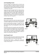
Arm Crowd Circuit
When the arm control lever is put in the crowd mode, the left
side pilot valve generates secondary pressure that is transmitted
to the AM1 and AM2 spools of the control valve simultaneously.
When secondary pilot pressure reaches 7 - 9 kg/cm
2
(100 - 130
psi), the arm control valve spools AM1 and AM2 open. Output
flow from both halves of the pump assembly is directed to the
arm cylinder.
When working in the arm crowd mode, under certain conditions,
oil in the arm cylinder could suddenly be forced out by the weight
of the arm and bucket. Insufficient oil flow to the cylinder could
lead to cavitation in the cylinder and/or surging or irregular
movement. This is prevented by a regeneration valve attached
to the control valve which maintains the balance between oil
flowing into the cylinder and oil flowing out.
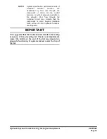
Arm Dump Circuit
When the arm control lever is put in "dump" mode, the left side
pilot valve generates secondary pilot pressure that goes to both
spools AM1 and AM2 of the control valve simultaneously.
When pilot pressure reaches 7 - 9 kg/cm
2
(100 - 130 psi), the
control spools open, allowing oil from PUMP (F) and PUMP (R)
to flow to the arm cylinder.
PUMP(F)
PUMP(R)
PL
PR
TL
CONTROL
VALVE(L)
ARM
CYLINDER
CONTROL
VALVE(R)
AMD1
AM1
REGENERATION VALVE
AM2
FG015149
PILOT VALVE
Figure 4
PUMP(F)
PUMP(R)
TL
PR
AM2
PL
CONTROL
VALVE(L)
ARM
CYLINDER
CONTROL
VALVE(R)
AMD1
FG015150
AMD2
PILOT VALVE
AM1
Figure 5
Summary of Contents for DX140LCR
Page 1: ...Shop Manual DX140R DX140LCR Serial Number 5001 and Up K1049551BE July 2011 EXCAVATOR ...
Page 2: ......
Page 4: ......
Page 6: ......
Page 9: ...1Safety ...
Page 10: ......
Page 12: ...SP002281 Track Excavator Safety Page 2 MEMO ...
Page 14: ...SP002281 Track Excavator Safety Page 4 MEMO ...
Page 57: ...1Specifications ...
Page 58: ......
Page 60: ...SP002379 Specification for DX140LCR Page 2 MEMO ...
Page 62: ...SP002379 Specification for DX140LCR Page 4 MEMO ...
Page 83: ...1General Maintenance ...
Page 84: ......
Page 86: ...SP000016 General Maintenance Procedures Page 2 MEMO ...
Page 88: ...SP000016 General Maintenance Procedures Page 4 MEMO ...
Page 104: ...SP000016 General Maintenance Procedures Page 20 ...
Page 105: ...SP000813 Page 1 Standard Torques SP000813 STANDARD TORQUESSP000813 Standard Torques Edition 1 ...
Page 106: ...SP000813 Standard Torques Page 2 MEMO ...
Page 108: ...SP000813 Standard Torques Page 4 MEMO ...
Page 121: ...1Upper Structure ...
Page 122: ......
Page 123: ...SP002282 Page 1 Cabin SP002282 CABIN SP002282 Cabin Edition 1 ...
Page 124: ...SP002282 Cabin Page 2 MEMO ...
Page 126: ...SP002282 Cabin Page 4 MEMO ...
Page 136: ...SP002282 Cabin Page 14 ...
Page 137: ...SP001939 Page 1 Counterweight SP001939 COUNTERWEIGHT SP001939 Counterweight Edition 1 ...
Page 138: ...SP001939 Counterweight Page 2 MEMO ...
Page 140: ...SP001939 Counterweight Page 4 MEMO ...
Page 147: ...SP001940 Page 1 Fuel Tank SP001940 FUEL TANK SP001940 Fuel Tank Edition 1 ...
Page 148: ...SP001940 Fuel Tank Page 2 MEMO ...
Page 150: ...SP001940 Fuel Tank Page 4 MEMO ...
Page 162: ...SP001940 Fuel Tank Page 16 ...
Page 164: ...SP000021 Fuel Transfer Pump Page 2 MEMO ...
Page 166: ...SP000021 Fuel Transfer Pump Page 4 MEMO ...
Page 171: ...SP001856 Page 1 Swing Bearing SP001856 SWING BEARING SP001856 Swing Bearing Edition 1 ...
Page 172: ...SP001856 Swing Bearing Page 2 MEMO ...
Page 174: ...SP001856 Swing Bearing Page 4 MEMO ...
Page 180: ...SP001856 Swing Bearing Page 10 ...
Page 182: ...SP000921 Swing Reduction Gear Page 2 MEMO ...
Page 184: ...SP000921 Swing Reduction Gear Page 4 MEMO ...
Page 186: ...SP000921 Swing Reduction Gear Page 6 ...
Page 192: ...SP000921 Swing Reduction Gear Page 12 Figure 7 ...
Page 222: ...SP000921 Swing Reduction Gear Page 42 ...
Page 223: ...1Lower Structure and Chassis ...
Page 224: ......
Page 225: ...SP001941 Page 1 Track Assembly SP001941 TRACK ASSEMBLY SP001941 Track Assembly Edition 1 ...
Page 226: ...SP001941 Track Assembly Page 2 MEMO ...
Page 228: ...SP001941 Track Assembly Page 4 MEMO ...
Page 234: ...SP001941 Track Assembly Page 10 Track Shoe 8 7 2 10 11 9 FG003910 1 3 6 4 5 Figure 4 ...
Page 255: ...1Engine and Drive Train ...
Page 256: ......
Page 257: ...SP001671 Page 1 QSB4 5 Engine SP001671 QSB4 5 ENGINESP001671 QSB4 5 Engine Edition 1 ...
Page 258: ...SP001671 QSB4 5 Engine Page 2 MEMO ...
Page 264: ...SP001671 QSB4 5 Engine Page 8 QSB4 5 ENGINE Figure 1 ...
Page 311: ...SP001671 Page 55 QSB4 5 Engine Figure 32 ...
Page 532: ...SP001326 Drive Coupling Main Pump Page 2 MEMO ...
Page 534: ...SP001326 Drive Coupling Main Pump Page 4 MEMO ...
Page 536: ...SP001326 Drive Coupling Main Pump Page 6 ...
Page 542: ...SP001326 Drive Coupling Main Pump Page 12 ...
Page 543: ...1Hydraulics ...
Page 544: ......
Page 546: ...SP001942 Hydraulic System Troubleshooting Testing and Adjustment Page 2 MEMO ...
Page 580: ...SP001942 Hydraulic System Troubleshooting Testing and Adjustment Page 36 ...
Page 581: ...SP000028 Page 1 Accumulator SP000028 ACCUMULATOR SP000028 Accumulator Edition 1 ...
Page 582: ...SP000028 Accumulator Page 2 MEMO ...
Page 584: ...SP000028 Accumulator Page 4 MEMO ...
Page 590: ...SP000029 Center Joint Swivel Page 2 MEMO ...
Page 592: ...SP000029 Center Joint Swivel Page 4 MEMO ...
Page 599: ...SP000030 Page 1 Cylinders SP000030 CYLINDERS SP000030 Cylinders Edition 1 ...
Page 600: ...SP000030 Cylinders Page 2 MEMO ...
Page 602: ...SP000030 Cylinders Page 4 MEMO ...
Page 628: ...SP000030 Cylinders Page 30 ...
Page 629: ...SP001943 Page 1 Swing Motor SP001943 SWING MOTOR SP001943 Swing Motor Edition 1 ...
Page 630: ...SP001943 Swing Motor Page 2 MEMO ...
Page 632: ...SP001943 Swing Motor Page 4 MEMO ...
Page 664: ...SP001943 Swing Motor Page 36 ...
Page 665: ...SP001346 Page 1 Travel Moter SP001346 TRAVEL MOTER SP001346 Travel Moter Edition 1 ...
Page 666: ...SP001346 Travel Moter Page 2 MEMO ...
Page 671: ...SP001346 Page 7 Travel Moter EXTERNAL DIMENSIONS Figure 1 ...
Page 672: ...SP001346 Travel Moter Page 8 GENERAL DESCRIPTION Figure 2 ...
Page 680: ...SP001346 Travel Moter Page 16 Figure 6 ...
Page 736: ...SP001346 Travel Moter Page 72 ...
Page 737: ...SP001945 Page 1 Main Pump SP001945 MAIN PUMP SP001945 Main Pump Edition 1 ...
Page 738: ...SP001945 Main Pump Page 2 MEMO ...
Page 740: ...SP001945 Main Pump Page 4 ...
Page 752: ...SP001945 Main Pump Page 16 Installation of Tandem Type Double pump Figure 25 ...
Page 753: ...SP001945 Page 17 Main Pump Construction of Tandem Type Double Pump Figure 26 ...
Page 756: ...SP001029 Main Control Valve Page 2 MEMO ...
Page 758: ...SP001029 Main Control Valve Page 4 MEMO ...
Page 760: ...SP001029 Main Control Valve Page 6 GENERAL DESCRIPTION Figure 1 ...
Page 774: ...SP001029 Main Control Valve Page 20 Figure 19 Figure 20 ...
Page 806: ...SP001646 Remote Control Valve Work Lever Joystick Page 2 MEMO ...
Page 808: ...SP001646 Remote Control Valve Work Lever Joystick Page 4 MEMO ...
Page 810: ...SP001646 Remote Control Valve Work Lever Joystick Page 6 ...
Page 812: ...SP001646 Remote Control Valve Work Lever Joystick Page 8 Parts List Figure 1 ...
Page 826: ...SP001646 Remote Control Valve Work Lever Joystick Page 22 ...
Page 828: ...SP002262 Travel Control Valve with Damper Page 2 MEMO ...
Page 830: ...SP002262 Travel Control Valve with Damper Page 4 MEMO ...
Page 832: ...SP002262 Travel Control Valve with Damper Page 6 ...
Page 836: ...SP002262 Travel Control Valve with Damper Page 10 ...
Page 838: ...SP002262 Travel Control Valve with Damper Page 12 Parts List Figure 3 ...
Page 852: ...SP002262 Travel Control Valve with Damper Page 26 ...
Page 854: ...SP001944 Solenoid Valve Assembly Page 2 MEMO ...
Page 856: ...SP001944 Solenoid Valve Assembly Page 4 MEMO ...
Page 863: ...SP001944 Page 11 Solenoid Valve Assembly Solenoid Valve Diagram Figure 3 ...
Page 866: ...SP001944 Solenoid Valve Assembly Page 14 ...
Page 868: ...SP000192 Breaker EPPR Valve Opt Page 2 MEMO ...
Page 870: ...SP000192 Breaker EPPR Valve Opt Page 4 MEMO ...
Page 880: ...SP002383 Hydraulic Schematic DX140LCR Page 2 MEMO ...
Page 882: ...SP002383 Hydraulic Schematic DX140LCR Page 4 MEMO ...
Page 884: ...SP002383 Hydraulic Schematic DX140LCR Page 6 ...
Page 886: ...1Electrical System ...
Page 887: ......
Page 889: ...SP001949 Electrical System Page 2 MEMO ...
Page 892: ...SP001949 Electrical System Page 5 MEMO ...
Page 948: ...SP001949 Page 61 Electrical System ...
Page 962: ...SP001949 Page 75 Electrical System ...
Page 1001: ...SP002271 Electrical Schematic DX140LCR Page 2 MEMO ...
Page 1003: ...SP002271 Electrical Schematic DX140LCR Page 4 MEMO ...
Page 1005: ...SP002271 Electrical Schematic DX140LCR Page 6 ...
Page 1007: ...1Attachments ...
Page 1008: ......
Page 1009: ...SP002378 Page 1 Boom and Arm SP002378 Boom and Arm Edition 1 ...
Page 1010: ...SP002378 Boom and Arm Page 2 MEMO ...
Page 1012: ...SP002378 Boom and Arm Page 4 MEMO ...
Page 1020: ...SP002378 Boom and Arm Page 12 ...
Page 1021: ...Bucket Page 1 SP000939 SP000939 BUCKET SP000939 1Bucket Edition 1 ...
Page 1022: ...Bucket SP000939 Page 2 MEMO ...
Page 1024: ...Bucket SP000939 Page 4 MEMO ...
Page 1031: ......
Page 1032: ...2905 Shawnee Industrial Way Suite 100 Suwanee GA 30024 ...