background image

29

 I 


USER MANUAL

Napake - nadaljevanje

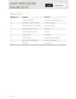
ERROR NUM.

100

101 

102

104

105

106

107

108

Reset door controller / Call service

Reset door controller / Call service

Reset door controller / Call service

Reset door controller / Call service

Wait 1 minute / Reset door controller / Call service

Replace upper left actuator

Replace lower left actuator

Replace upper right actuator

ERROR

SOLUTION

WINDING MOTOR

ACTUATORS

BRAKE

103

Reset door controller / Call service

END SWITCH

EC4 NOT READY

UPPER LEFT ACTUATOR

UPPER RIGHT ACTUATOR

FIRE INPUT

LOWER LEFT ACTUATOR

LIGHT AND SOUND 

DIAGNOSTICS 

109

Replace lower right actuator

LOWER RIGHT ACTUATOR

To preserve its properties the product has to be correctly stored as specified below:


• 

The door leaf/leaves have to be stored on special pallets that are usually used for 

  transporting 

glass;


• 

Store in a dry place;


• 

The door drives have to be stored on a storage ramp and must be protected against 


damage on the outer visible surfaces;


• 

During transport the door leaf/leaves have to be loaded on a pallet that is usually used for  

  transporting 

glass;


• 

The door leaf/leaves must be tied during transport so that they cannot fall over or brake;


• 

The door leaf/leaves have to be appropriately wrapped in cardboard or a similar material  


before they are loaded on the pallet, so that the profiles or glass do not get scratched or  


dented . The system units need to be protected in an appropriate package to prevent 


damage during transport .

TRANSPORT AND 

STORAGE

Summary of Contents for 300 A

Page 1: ...USER MANUAL AUTOMATIC SLIDING DOOR PRODUCT LINE 300 1 25 2016 product line...

Page 2: ......

Page 3: ...REDUNDANCY TESTING 14 FIRE SIGNAL 15 ELECTRIC LOCK EL5 16 FIRST STARTUP 17 TYPE 300 A 18 NORMAL OPERATION OF 300 A 18 ACTIVATION OF THE BREAK OUT FUNCTION 19 POSSIBILITY OF ENLARGING THE PASSAGE OPEN...

Page 4: ...ementation of the high technology allows for many various functions of opening and closing the door The locks prevent unwanted intrusion and the one way passage ensures selectivity Partial opening of...

Page 5: ...ist of an intelligently regulated modern drive mechanism The door controller allows you to use a wide range of accessories mode selectors motion and presence sensors safety sensors battery units elect...

Page 6: ...Do not allow door operation if repair or adjustment is necessary disconnect the power supply 230VAC and battery unit during maintenance works inside the drive change the door mode to STOP during the...

Page 7: ...30V 50 60Hz max 0 7m s depends on the weight of the leaves 300W IP54 6 3A slow 20 C do 50 C 90 15 years or at least 1 000 000 cycles glued 4 4 or 5 5 ESG 8 or 10mm insulated 3 3 9d 3 3 6k 9d 6k 5k 9d...

Page 8: ...door with break out system mechanical redundant 300 A door with break out system 300 C curved door 300 T telescopic door standard standard redundant standard redundant standard redundant standard redu...

Page 9: ...low repairs and maintenance only to professionally trained services use the system according to the user manual otherwise safety of people is at risk unauthorized interference with the system its oper...

Page 10: ...s door opens and remains open door operation in automatic mode door operation in automatic mode reduced opening door opens only with exit sensor door opens only with exit sensor reduced opening door s...

Page 11: ...after error and switch to STOP mode press for 6s COM21 COM21 is the basic mode selector for automatic sliding doors product line 300 The button serves to change the operating mode with a simple turn...

Page 12: ...door controller switches off the doors open and remain still in open position after the power failure The system automatically switches off when the battery voltage drops to a certain limit The syste...

Page 13: ...l no longer be possible 2 ENTRANCE into the building in CLOSED EXIT SUMMER or EXIT WINTER operating mode Entry into the building with the entry sensor is not possible Install an additional switching m...

Page 14: ...eeded if the doors are installed on escape routes The redundancy system is tested every twelve hours in mode EXIT or AUTO The door opens once and closes again in the test procedure The drive electric...

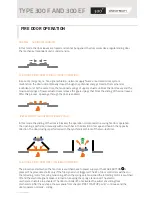
Page 15: ...and 300 EF MUST be connected to the fire central if it exists If the mode selector is not in the CLOSED position the doors will OPEN when the fire signal is triggered except for systems 300 F and 300...

Page 16: ...Door is locked mechanically when the red handle on the electric lock EL5 is in the LOCK position For unlocking the red handle on the electric lock EL5 has to be moved to the UNLOCK position It is pos...

Page 17: ...the position CLOSED when the doors are closed at the damper limit in a one leaf door or when the leaves lean against each other in double leaf doors 10 The doors will then slowly move to an open posit...

Page 18: ...EN button must be visible on the bolt of the sliding doors TYPE 300 A When the CLOSE mode is selected the door will lock electrically The sliding leaves must bolt so that we can block the break out fu...

Page 19: ...OUT FUNCTION The sliding and fixed wings open out in the direction of the emergency exit by physical force regardless of the position of the sliding wings If the sliding wings are in movement at the m...

Page 20: ...arrier preventing the fire to spcread from one sector to another INTENDED USE OF 300 EF DOORS FOR ESCAPE ROUTES AND EMERGENCY EXITS WITH BREAK OUT FUNCTION AND FIRE RESISTANCE The 300 EF projected aut...

Page 21: ...the sliding of the door is blocked the operation corresponds to a swing fire door operation The opening is performed manually with a touch bar in the direction of escape and hook in the opposite direc...

Page 22: ...rer will NOT take any responsibility for improper door function or any damage because of improperly configured settings by an unqualified person Settings on the automatic sliding doors product line 30...

Page 23: ...oor an obstacle during the movement The EC4 door controller has two light indicators They indicate the following LED1 main power supply LED2 battery power supply Door controller EC4 and mode selector...

Page 24: ...E PAUSE 3s 24 I USER MANUAL LIGHT AND SOUND DIAGNOSTICS SHORT PULSE follows after a long pulse and indicates number 1 Short pulse 0 1 s DURING ERRORS Interval flashing and beeping 0 5 s Example in fig...

Page 25: ...em call the service When an error occurs that cannot be eliminated If you cannot resolve the error by yourself and you need to close the door press and hold the WAKE BUTTON for 6 seconds This procedur...

Page 26: ...FETY SENSOR RESERVE ENTRY SAFETY SENSOR ACTIVE OVER 1 m ENTRY SENSOR ACTIVE OVER 1 MINUTE MONITORING EXIT SAFETY SENSOR MONITORING SIDE SAFETY SENSOR 1 EXIT SAFETY SENSOR ACTIVE OVER 1 m EXIT SENSOR A...

Page 27: ...try PIN code Increase single entry opening width Remove single entry contact Service needed WARNING SOLUTION NO BATTERY CONNECTED MONITORING SIDE SAFETY SENSOR 2 SIDE SAFETY SENSOR 2 ACTIVE OVER 1 m 2...

Page 28: ...rvice ERROR SOLUTION STARTUP TIMEOUT STARTUP OVERLOAD ENCODER OR MOTOR 70 Wait 1 minute Reset door controler Call service FIFO SM0 15 Wait 1 minute Reset door controler Call service 13 Replace memory...

Page 29: ...its properties the product has to be correctly stored as specified below The door leaf leaves have to be stored on special pallets that are usually used for transporting glass Store in a dry place Th...

Page 30: ...e doors with a wet cloth and non aggressive cleaners Do not clean the doors with a water jet Major refitting is not necessary during the lifespan of the automatic sliding doors product line 300 The re...

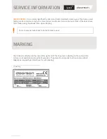
Page 31: ...f the device have to be made during the annual check up and testing Doors on escape routes have to be tested once a year The CE label is attached on the inner left or right end of the drive cover Labe...

Page 32: ......

Reviews: