VPRS-430 OPERATION MANUAL
Issue : 2009.03
ED : 1
VPRS-430 OPERATION MANUAL 22 /30
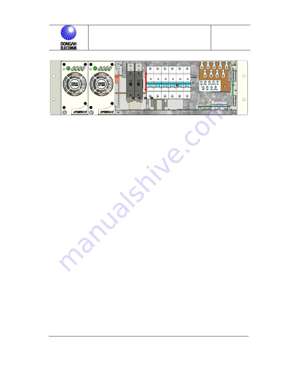
Figure 7. Battery Disconnect(Front panel Open View)
7 Rectifier System Operation & Stop Operation
7.1 Rectifier System Operation
①
Turn on the AC power switches at the rectifier unit top.
②
Yellow LED on each rectifier unit will be turned on.
③
Turn on the switch of each rectifier unit.
④
Turn on the power switch of the control unit.
⑤
Check if the rectifier system name displayed at the LCD of the control unit
matches the actual rectifier Shelf installed.
⑥
Check if the STATUS LED indicates normal.
7.2 Rectifier System Stopping (LOCAL)
①
Turn off the switch of each rectifier unit.
②
Yellow LED on each rectifier unit is turned on.
③
Turn off the main breaker at the distribution panel.
④
Turn off the power switch of the control unit.
7.3 Battery Temperature Compensation (BTC mode in TEMP ON)
As shown in the Rectifier Installation Manual, install the Battery Temperature
Compensating Probe near the battery Shelf.
Once the temperature probe is connected, and set to BTC mode, the system will
O
OFF


